(!)Due to Microsoft's end of support for Internet Explorer 11 on 15/06/2022, this site does not support the recommended environment.
- inCAD Library Home
- > No.000230 Adjustable Guide Mechanism
No.000230 Adjustable Guide Mechanism
62
62
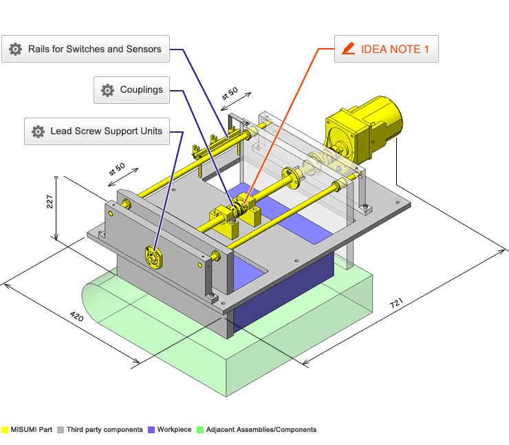
Easy adjustment using coupling, motor and lead screws.
Relevant category
- * Unit assembly Data consists of some sub-assemblies.
It is configured so that each sub-assembly unit can be used as it is or edited.
Application Overview
Purpose
- Purpose
- To automatically change the distance between workpiece guides during setup change.
- Operation
- By connecting right and left hand screw with coupling and rotating only one lead screw, the distance between guide plates is adjusted without changing the center of reference.
Points for use
- Thanks to the coupling that connects the lead screws, adjusting only one side will also adjust the side, maintaining the center between the guide plates.
Target workpiece
- Shape: cardboard box
- Size: W330 x D280 x H110 mm
- Weight: 2 kg
Design Specifications
Operating Conditions or Design Requirements
- Target workpiece width range: 230 to 330 mm
- Outer dimensions: W721 x D420 x H227 mm
Required Performance
- Lead Screw
Single pitch error:±0.02mm
Accumulated pitch error: ±0.15/300 mm
Allowable Load:33.8kg
Selection Criteria for Main Components
- Coupling
- A coupling with an allowable torque of 4 [N·m], small backlash backlash and an allowable torque of 0.66 [N·m] is selected.
Design Evaluation
Verification of main components
- Select motor, lead screws and linear bushings based on the workpiece load and workpiece collision load.
- Confirmation of thrust in axial direction
- Conditional value: workpiece mass W = 2kg, gravitational acceleration g = 9.8m/s², friction coefficient of lead screw μ = 0.21, lead of lead screw: R = 3mm = 0.003m, lead angle of lead screw: θ = 3.77°, rated torque of geared motor with reduction ratio i = 3: T = 0.66N·m, friction coefficient exerted on workpiece: δ = 0.5
- Screw efficiency η
η=(1-μ×tanθ)/(1+μ/tanθ)=(1-0.21×tan3.77)/(1+0.21/tan3.77)=0.24
Thrust of lead screw:F=2π×η×T/R=2π×0.24×0.66/0.003
=331.8N - Force required to move workpiece: P
P=M×g×σ=2×9.8×0.5=9.8N and F > P, the necessary force can be obtained.
- Allowable load of linear ball bushing when workpiece hits the guide
- Conditional value: linear bushing maximum horizontal distance X0 = 370.4 mm, linear bushing distance in transfer direction Y0 = 276 mm, distance between transfer axis and load position X1 = 180 mm, vertical distance between linear bushing axis and load position L0 = 170.5 mm, load applied when workpiece collides Wa = 40 N, basic rated static load of liner bushing C0 = 598 N, number of linear bushings to which load is applied when workpiece collides N = 2 pieces
- Load in transfer direction applied to linear bushing on collision side: Ps=(W/N)+{(X1×W)/2×X0}=(40/2)+{(180×40)/(2×370.4)}=29.72N
- Load in vertical direction applied to linear bushing on collision side: Pn={(L0×W)/(2×Y0)}={(170.5×40)/(2×276)}=12.36N
Therefore, resultant force applied to linear bushing:P=√(Ps2+Pn2)=32.19N<598=CO (Bushing Dynamic load rating)
Other Design Consideration
- For applications where only small adjustments are needed it is possible to substitute one left and one right hand screw with right/left hand screw and avoid center block and coupling.
Explore Similar Application Examples
Page
-
/
-
-
Relevant category
-
Relevant category


