(!) Since support from Microsoft will end on January 14th, 2020, Windows 7 will be excluded from the recommended environment from December 15th, 2019 on this site. Vì lý do Microsoft kết thúc hỗ trợ cho Windows 7 vào ngày 14/01/2020, Windows 7 sẽ là hệ điều hành không được khuyến khích sử dụng với trang web này từ ngày 15/12/2019.
Over 300 design application ideas
collected from dozens of industries!
Log in to download free CAD models.
Download CAD for the entire application example!
Click the Good IDEA! Button when you like an application example!
*Can only be clicked once per application example.
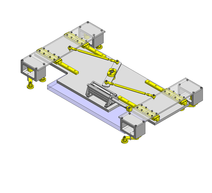
4 direction simultaneous clamping with a cylinder and a linkage mechanism.
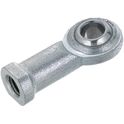
Product name | Rod End Bearings - Standard |
---|---|
Part number | PHSCM5 |
Suitable for applying to swinging link mechanism parts.
■Rod End Coupling Rods - Both Ends Threaded
Material | Surface Treatment | Accessory (Hex Nut) | |
---|---|---|---|
Material | Surface Treatment | ||
1045 Carbon Steel | Black Oxide | 1045 Carbon Steel | Trivalent Chromate |
Electroless Nickel Plating | |||
304 Stainless Steel | − | 304 Stainless Steel | − |
■Sizes and Dimensions
Screw Dia. (Coarse) | Hex Size | Overall Length (1mm Increments) | Thread Length |
---|---|---|---|
M3 | 6 | 25〜39 | 8 |
40〜300 | 15 | ||
M4 | 7 | 35〜49 | 12 |
50〜400 | 20 | ||
M5 | 8 | 40〜59 | 13 |
60〜600 | 25 | ||
M6 | 10 | 50〜69 | 17 |
70〜600 | 30 | ||
M8 | 13 | 60〜89 | 23 |
90〜1000 | 40 | ||
M10 | 17 | 70〜109 | 28 |
110〜1000 | 50 | ||
M12 | 19 | 80〜129 | 33 |
130〜1000 | 60 | ||
M14 | 21 | 130〜1000 | 60 |
M16 | 24 | 170〜1000 | 80 |
M18 | 27 | 170〜1000 | 80 |
Product name | Links - Angled, 3 Hole |
---|---|
Part number | LKBM6-L50-S50-Q90-H6-HA6-T6 |
Features | Angled links are available. |
Suitable for limiting 2-axis direction with bearings.
■Links - Angled
Material | Surface Treatment |
---|---|
1018 Carbon Steel | Black Oxide |
Electroless Nickel Plating |
■Sizes and Dimensions
Main Shaft Bore Dia. | Bend Angle | Plate Thickness | Arm 1 | Arm 2 | ||||||
---|---|---|---|---|---|---|---|---|---|---|
1° Increments | Hole Type | Hole Dia. (Selectable) | Distance between Fulcrum and Main Shaft | Hole Type | Hole Dia. (Selectable) | Distance between Fulcrum and Main Shaft | ||||
φ4 | 90〜180 | 5 ・ 6 | Precision Hole ・ Tapped Hole | φ3 φ4 φ5 φ6 φ8 φ10 φ12 φ16 | M3 M4 M5 M6 M8 M10 M12 M16 | 40〜100 (1mm Increments) | Precision Hole ・ Tapped Hole | φ3 φ4 φ5 φ6 φ8 φ10 φ12 φ16 | M3 M4 M5 M6 M8 M10 M12 M16 | 30〜100 (1mm Increments) |
φ5 | ||||||||||
φ6 | ||||||||||
φ8 | ||||||||||
φ10 | ||||||||||
φ12 | ||||||||||
φ14 | ||||||||||
φ15 |
* Please see the product pages for detailed dimensions.
■Accuracy of Links
Main Shaft Bore Dia. Tolerance: H7
Precision Hole Dia. Tolerance: H7
Product name | Silicon Rubber / Urethane Molded Bearings - Flat |
---|---|
Part number | UMBB6-28 |
Urethane/Rubber will prevent damage to fixture.
■Urethane Molded Bearings - Flat, Shape A
Tire Section | Bearing Material | |||
---|---|---|---|---|
Material | Hardness | Color | Steel | Stainless Steel |
(52100 Bearing Steel) | (440C Stainless Steel) | |||
Urethane | Shore A95 | Black | ○ | ○ |
White | ○ | ○ | ||
Shore A90 | Black | ○ | ○ | |
White | ○ | ○ | ||
Shore A70 | Black | ○ | ○ | |
White | ○ | ○ | ||
Shore A50 | Black | ○ | − | |
White | ○ | − | ||
Antistatic Urethane | Shore A90 | Gray | ○ | − |
■Sizes and Dimensions
I.D. | O.D. | Width | Bearing Used |
---|---|---|---|
φ3 | φ10 | 3 | W683ZZA |
φ12 | |||
φ4 | φ13 | 4 | W684AX50ZZ |
φ16 | 5 | 624ZZ | |
φ5 | φ16 | WBC5−13ZZ | |
φ20 | 625ZZ | ||
φ6 | φ20 | 696ZZ | |
φ28 | 6 | 626ZZ | |
φ8 | φ28 | 7 | 608ZZ |
φ30 | 608ZZ | ||
φ10 | φ30 | 8 | 6000ZZ |
φ40 | 9 | 6200ZZ | |
φ15 | φ40 | 6002ZZ | |
φ45 | 11 | 6202ZZ | |
φ20 | φ45 | 9 | 6904ZZ |
φ55 | 14 | 6204ZZ | |
φ25 | φ65 | 15 | 6205ZZ |
■Load Capacity of Urethane Molded Bearing - Flat
I.D. | O.D. | Allowable Load N | |||
---|---|---|---|---|---|
Shore A95 | Shore A90 | Shore A70 | Shore A50 | ||
φ3 | φ10 | 38 | 28 | 9 | 4 |
φ12 | 53 | 34 | 10 | 6 | |
φ4 | φ13 | 66 | 44 | 13 | 7 |
φ16 | 79 | 59 | 16 | 6 | |
φ5 | φ16 | 79 | 16 | ||
φ20 | 102 | 78 | 20 | 9 | |
φ6 | φ20 | 114 | 23 | 15 | |
φ28 | 218 | 157 | 44 | 39 | |
φ8 | φ28 | 208 | 42 | 35 | |
φ30 | − | 176 | 81 | 65 | |
φ10 | φ30 | 94 | 51 | ||
φ40 | − | 274 | 136 | 93 | |
φ15 | φ40 | 122 | 96 | ||
φ45 | − | 343 | 109 | 102 | |
φ20 | φ45 | 130 | 98 | ||
φ55 | − | 490 | 225 | 176 | |
φ25 | φ65 | − | 750 | 333 | 250 |
Two plates connected together with a linkage mechanism are operated by one cylinder. The plates are moved to the outside and returned to the center. The work piece is centered by the roller of the bell crank type linkage.
Thank you for downloading the data.
Click the Good IDEA! button when you find interesting design tips.
This data is utilized in order to list more useful application examples in the future.
* The part in the frame is a sub-assembly unit.
MISUMI Vietnam Company Limited, Legal Representative: Tomohiro Watanabe,
phone: 0222-361-1555, e-mail: cs@misumi.com.vn, Enterprise Code: 0107514576,
Date of Issuance: 22 July 2016, Place of Issuance: Bac Ninh, Business Certificate No. 6573041568-KD dated 27 September 2016 issued by the People's Committee of Bac Ninh
Công ty TNHH MISUMI Việt Nam, Đại diện theo pháp luật: Tomohiro Watanabe,
Điện thoại: 0222-361-1555, e-mail: cs@misumi.com.vn, Mã số doanh nghiệp: 0107514576,
ngày cấp 22/7/2016, nơi cấp: Bắc Ninh, Giấy phép kinh doanh số: 6573041568-KD ngày cấp 27/9/2016 bởi UBND tỉnh Bắc Ninh
Copyright © MISUMI Corporation All Rights Reserved.