(!)Due to Microsoft's end of support for Internet Explorer 11 on 15/06/2022, this site does not support the recommended environment.
- inCAD Library Home
- > No.000164 Push Position Switch Mechanism
No.000164 Push Position Switch Mechanism
14
14
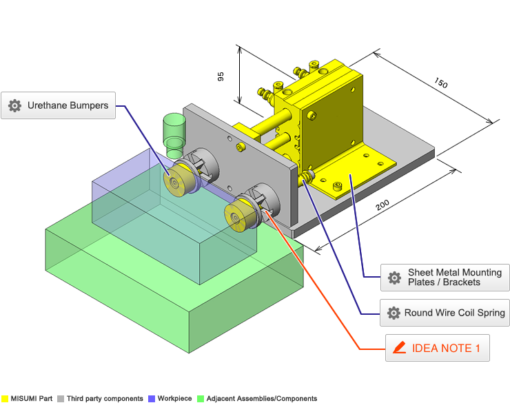
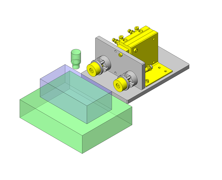
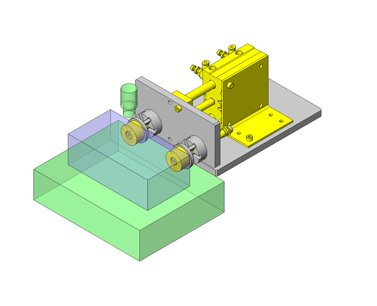
Easily switchable horizontal position via spring, pusher switch, and urethane bumper.
Relevant category
- * Unit assembly Data consists of some sub-assemblies.
It is configured so that each sub-assembly unit can be used as it is or edited.
Application Overview
Purpose
- Purpose
- Fixed stroke cylinder positions workpieces of different sizes.
- Operation
- This mechanism is installed on both sides of the workpiece.
Points for use
- The clamping distance can be adjusted.
The initial position is set by adjusting the height of the stopper and fixing it with a nut.
Target workpiece
- The widths of the workpiece differ depending on the model.
Different widths: 3 positions - Width (1): W80mm
- Width (2): W86mm
- Width (3): W92mm
Design Specifications
Operating Conditions or Design Requirements
- Outer dimensions: W200 x D150 x H95mm
Required Performance
- Positioning accuracy: ±0.5mm
Selection Criteria for Main Components
- A compression spring is chosen based on the operating force and pulling power of the stopper/knob.
Design Evaluation
Verification of main components
- The workpiece retaining force and the operating force of the knob with a claw are verified based on the selected spring load.
- Confirmation of operating force of knob with a claw
- Conditional Value:
Different widths: 3 positions
Height (1): W80mm
Height (2): W86mm
Height (3): W92mm
Spring constant: K = 0.29N/mm
Initial spring contraction amount: L1 = 7mm
Adjustment amount: L2 = 6mm (3 steps by 3-mm increments)
Distance from the stopper end face to the tip of the claw of the knob with a claw in Height (1) state: L3 = 2mm
- Conditional Value:
- Retaining force at each step
- Spring tension in Height (3) state: P1 = K x L1, therefore, P1 = 0.29 x 7 = 2.03N
Spring tension in Height (2) state: P2 = K x (L1 + L2), therefore, P2 = 0.29 x (7 + 3) = 2.9N
Spring tension in Height (1) state: P3 = K x (L1 + L2 x 2), therefore, P3 = 0.29 x (7 + 3 x 2) = 3.77N
- Spring tension in Height (3) state: P1 = K x L1, therefore, P1 = 0.29 x 7 = 2.03N
- Operating force
- Distance needed to remove the claw of the knob with a claw from the stopper:
L4=(L1+L2×2+L3)=7+3×2+2=15mm
The operating force for step change: F1 = K x L4, therefore,
F1=0.29×15=4.35N
- Distance needed to remove the claw of the knob with a claw from the stopper:
Other Design Consideration
- The accuracy of each height is determined by the manufacturing quality of the stopper.
Explore Similar Application Examples
Page
-
/
-
-
Relevant category


