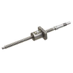
Rolled Ball Screw
| Product name | Precision Ball Screws |
| Part number | BSS1505-500 |
| Features | Smallest Nut Outer Diameter |
* Orange colored cells in the table below indicate the part numbers used in this example.
Selection criteria
Suitable for med. accuracy linear motion drive.
Back to page top
Available sizes
■Precision Ball Screws
| Screw shaft | Nut |
| Material | Hardness | Screw DIA.(mm) | Lead(mm) | Overall length(mm) | Material | Hardness |
| 4115 Alloy Steel | Carburized
58~62HRC | φ8 | 2 | 100-210 | 4130 Alloy Steel | Carburized
58~62HRC |
| φ10 | 2 | 100-315 |
| 4150 Alloy Steel | Induction hardened
58~62HRC | 4 | 150-380 |
| 10 | 150-450 |
| 4115 Alloy Steel | Carburized
58~62HRC | φ12 | 2 | 150-445 |
| 4150 Alloy Steel | Induction hardened
58~62HRC | 4 | 150-400 |
| 5 | 150-450 |
| 10 | 200-600 |
| φ15 | 5 | 150-1095 |
| 10 | 200-1095 |
| 20 | 230-1095 |
| φ20 | 5 | 200-1000 |
| 10 | 250-1500 |
| 20 |
| φ25 | 5 | 300-995 |
| 10 | 300-1500 |
| 20 |
■Features of Compact nut
Compact nut O.D.
Suitable for limited space applications
Back to page top
Selection steps
■Ball screw selection steps
- Determine application conditions
- (Moving mass, feed rate, motion pattern, screw rotary speed, mounting orientation (horizontal or vertical), life, positioning accuracy)
↓
- Temporarily select ball screw specifications
- (Based on app. conditions, ball screw accuracy grade (C3~C10), screw shaft DIA., lead, screw shaft length are temporarily selected.)
↓
- Basic Safety Check
-
- ● Allowable axial load
- ● Allowable max. speed
- ● Life
↓
- Evaluate in accordance with the required performance
-
- ● Screw shaft rigidity
- ● Change in life due to temperature
Back to page top
Accuracy Info
■Ball screw accuracy
| Screw shaft DIA. | Lead | Axial
clearance | Twist
direction | Nut pilot
tolerance | (1) (2) | (3) | (4) (5) | (6) | (7) |
Runout tolerance
(Max.) | Runout tolerance
(Max.) | Perpendicularity tolerance
(Max.) | Perpendicularity tolerance
(Max.) | Runout tolerance
(Max.) |
| φ8 | 2 | 0.005 or less | Right | -0.007/-0.020 | 0.011 | 0.011 | 0.005 | 0.010 | 0.012 |
| φ10 | 2・4・10 |
| φ12 | 2・4・5・10 |
| φ15 | 5・10・20 | -0.009/-0.025 | 0.012 | 0.012 | 0.011 | 0.015 |
| φ20 | 5・10・20 |
| φ25 | 5・10 | 0.013 | 0.013 | 0.013 | 0.019 |
| 20 | -0.010/-0.029 |
(mm)
| Screw shaft DIA. | (8) Runout tolerance (Max.) / Screw shaft length |
| -125 | 126-200 | 201-315 | 316-400 | 401-500 | 501-630 | 631-800 | 801-1000 | 1001-1250 | 1251- |
| φ8 | 0.035 | 0.050 | 0.065 | - | - | - | - | - | - | - |
| φ10 | 0.040 | 0.055 | 0.065 | 0.080 | 0.090 |
| φ12 |
| φ15 | - | 0.045 | 0.055 | 0.060 | 0.075 | 0.090 | 0.120 | 0.150 | 0.190 |
| φ20 |
| φ25 | - | 0.040 | 0.045 | 0.050 | 0.060 | 0.070 | 0.085 | 0.100 | 0.130 |
Back to page top
Performance info.
■Ball screw load ratings
| Screw shaft DIA. | Lead | Basic load ratings |
| C (Dynamic) kN | Co (Static) kN |
| φ8 | 2 | 1.95 | 2.6 |
| φ10 | 2 | 2.25 | 3.3 |
| 4 | 3.35 | 5.9 |
| 10 | 2.2 | 3.5 |
| φ12 | 2 | 2.45 | 4.1 |
| 4 | 3.6 | 6.75 |
| 5 | 5.95 | 9.8 |
| 10 | 3.85 | 5.9 |
| φ15 | 5 | 6.9 | 12.5 |
| 10・20 | 4.4 | 7.9 |
| φ20 | 5 | 8.35 | 17.5 |
| 10 | 13.5 | 25.1 |
| 20 | 9.2 | 16.2 |
| φ25 | 5 | 9.4 | 22.2 |
| 10 | 16.1 | 33.4 |
| 20 | 10.4 | 20.1 |
Back to page top
Technical calculations
■Ball screw life calculations
Ball screw life time is calculated by the following formula.
- C: Basic dynamic load rating (N)
- Pm: Average axial load (N)
- Nm: Average rotational speed (min-1)
- fw: Operation factor
- Steady operation without impact fw=1.0~1.2
- Normal operation fw=1.2~1.5
- Operation with impacts fw=1.5~2.0
- Definition of basic dynamic load rating -
Basic dynamic load rating is an axial load applied on ball screws where a group of the same ball screws
are operated and 90% of the specimen will reach 1,000,000 (10^6) rotations without showing any flaking.
- About average axial load and average rotational speed. -
This needs to be calculated based on the motion pattern.
While it is difficult to accurately obtain load condition, etc, we do know that the ball screws operating life is inversely proportional to the third power of the load.
- Motion pattern example - (T1+T2+T3=100%)
Motion
pattern | Axial load | Rotational
speed | Time
proportion |
|
| A | P1N | N1min^-1 | t1% |
| B | P2N | N2min^-1 | t2% |
| C | P3N | N3min^-1 | t3% |
Back to page top
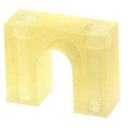
Ball Screw Stopper
| Product name | Stopper for Ball Screws |
| Part number | BSTS12 |
* Orange colored cells in the table below indicate the part numbers used in this example.
Selection criteria
Urethane stopper for overrun protection
Back to page top
Available sizes
■Stopper for Ball Screws
(mm)
| Material | Hardness | Applicable
ball screw DIA. | Stopper plate thickness | Ball screw shaft
center height |
Ether based
polyurethane | Shore A90 | φ8 | 15 | 17 |
| φ10 | 18 | 23, 25 |
| φ12 | 18 | 23, 25 |
| φ15 | 20 | 26, 28, 30 |
| φ20 | 20 | 30 |
| φ25 | 20 | 35 |
Back to page top
Linear Guide
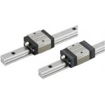
| Product name | Linear Guides for Medium Load |
| Part number | SV2R-MX24-520-WC |
| Features | Compliant with the industry standard specifications. |
* Orange colored cells in the table below indicate the part numbers used in this example.
Selection criteria
Standard block, Medium load, normal clearance linear guide
Back to page top
Available sizes
■Linear Guides for Medium Load
| Material | Hardness | Overall height(mm) | Rail length(mm) |
| Carbon steel | 58HRC~ | 24 | 160-1480 |
| 28 | 220-1960 |
| 33 | 220-1960 |
Back to page top
Selection steps
Linear guide selection steps
- Determine application conditions
- (Mass of moving body, Feed rate, Motion pattern, Life)
↓
- Selection of linear guide specifications
- (Temporarily select linear guide load type, overall height,
rail length based on the application condition)
↓
- Safety Check
-
- Load capacity
- Life
- Preload
Back to page top
Accuracy Info
Preload and accuracy reference Standards
(μm)
| Dimension tolerance of H | ±100 |
| Pair variation of H | 20 |
| Dimension tolerance of W2 | ±100 |
Pair variation
of W2 | H24・28 | 20 |
| H33 | 30 |
(μm)
| Rail length |
| -250 | 251-400 | 401-500 | 501-630 | 631-800 | 801-1000 | 1001-1250 | 1251-1600 | 1601-2000 |
Running
Parallelism | 7 | 12 | 14 | 18 | 21 | 23 | 25 | 27 | 28.5 |
Back to page top
Performance info.
■Linear guide load ratings (For med. loads, Normal clearance, Standard grade)
| Overall height | Basic load rating | Allowable static moment |
| C (Dynamic) kN | C 0 (Static) kN | MA・MB
N・m | Mc
N・m |
| 24 | 5.0 | 8.23 | 33 | 57 |
| 28 | 7.2 | 12.1 | 58 | 135 |
| 33 | 11.7 | 19.6 | 109 | 225 |

Back to page top
Technical calculations
Linear guide life calculations
- Operating Life
- When a linear guide is loaded in linear reciprocating motion, scaly damage called flaking can appear. This is due to material fatigue because the stress works on the rolling elements and contact surfaces constantly. Total travel distance until the first flaking occurs is the life of the linear guide.
- Rated life
- Rated life is the total travel distance that 90% of same linear guides, under the same conditions, can reach with no occurrence of flaking damage. Rated life can be obtained from the Basic Dynamic Load Rating and the actual load applied on the linear blocks, as shown below.
-

- Load must be calculated before actually using a linear guide. To obtain load during linear reciprocating motion, it is necessary to consider vibration, impact during motion and the distribution status of the linear guides. The operating environment temperature also effects the life of these parts. when taking these conditions into considiration, the calculation will be:
-

- L: Rated life (km)
- fH: Hardness factor (see Fig-1)
- fT: Temperature factor (see Fig-2)
- fC: Contact factor (see Table-1)
- fW: Load factor (see Table-2)
- C: Basic dynamic load rating (N)
- P: Applicable load (N)
- Hardness Factor (fH)
-

For Linear Guide applications, sufficient hardness is required for ball contact shafts. Inappropriate hardness causes less allowable load, resulting in shorter life. Please correct the rated life according to the hardness factors.
- Temperature Factor (fT)
-
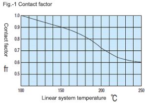
If the linear guide temperature exceeds 100°C, the linear guide and rail hardness decreases. This results in a lower allowable load and a shorter life when compared to an application at room temperature. Please correct the rated life according to the temperature factor.
*Please use linear guide under the allowable temperature shown on each product page.
- Contact Factor (fC)
-
Table-1. Contact factor
| Number of Linear Guide Blocks on One Rail | Contact Fator fC |
| 1 | 1.00 |
| 2 | 0.81 |
| 3 | 0.72 |
| 4 | 0.66 |
| 5 | 0.61 |
For actual applications, more than 2 blocks are generally used per rail. In this case, load applied to each block varies depending on machining precision but is not uniformly distributed. As a result, the per-block allowable load varies depending on the number of blocks per rail. Please correct the rated life according to Table 1 : Contact Factor
- Load factor (fW)
-
Table-2. Load factor
| Condition of Use | fw |
No external shocks or vibrations and
speed is low 15m/min or less | 1.0-1.5 |
No significant shocks or vibration and
med. speed 60m/min or less | 1.5-20 |
External shocks and vibrations exist
and the speed is high 60m/min or over | 2.0-3.5 |
To calculate load applied to the linear system, in addition to object weight, inertia force attributed to motion velocity, moment loads and variations of each over time must be obtained. However, for reciprocating motion applications, it is difficult to obtain accurate calculations due to the effects of the vibrations and shocks. Therefor, use Table-2 in order to simplify the Life Calculations.
- Applicable load calculation method
- When load is applied to a block, convert moment load into applied load using the following formula:
-
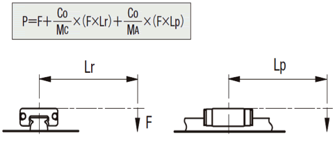
- P: Applicable load (N)
- F: Downward load (N)
- C0: Static load rating (N)
- MA: Allowable static moment - Pitching direction (N・m)
- MC: Allowable static moment - Rolling direction (N・m)
- Lp: Load point distance (m) in pitching direction
- Lr: Load point distance (m) in rolling direction
Back to page top
IDEA NOTE Cost reduction by effective use of purchased components
Design steps can be reduced by utilizing ball screws, support units and height adjusting blocks for linear guides.


