(!)Due to Microsoft's end of support for Internet Explorer 11 on 15/06/2022, this site does not support the recommended environment.

- inCAD Library Home
- > No.000181 Reduces the Thrust Load of a Small-size Motor Shaft
No.000181 Reduces the Thrust Load of a Small-size Motor Shaft
27
27
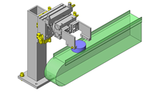
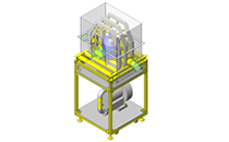
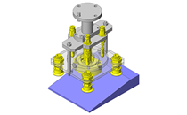
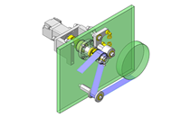
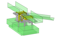
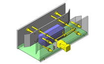
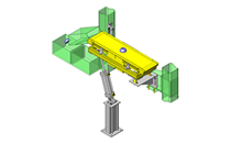
Reducing the thrust load without using a coupling.
Relevant category


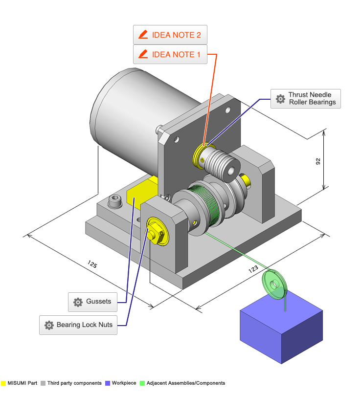
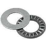
Thrust Needle Roller Bearings
| Product name | Thrust Needle Roller Bearings |
|---|---|
| Part number | BA0619 |
* Orange colored cells in the table below indicate the part numbers used in this example.
Selection criteria
Suitable item to support thrust load
Available sizes
■Thrust Needle Roller Bearings
Material: 52100 Bearing Steel
| (Name No.) | Thrust Needle Roller with Retainer | Thrust Washer x 2 | ||||||||||
|---|---|---|---|---|---|---|---|---|---|---|---|---|
| Hole Dia. | O.D. | Overall Thickness | Hole Dia. | O.D. | Plate Thickness | |||||||
| Tolerance | Tolerance | Tolerance | Tolerance | Tolerance | Tolerance | |||||||
| BA0414 | φ4 | +0.14/ +0.02 | φ14 | -0.095/ -0.365 | 2 | 0/-0.01 | φ4 | +0.2/ +0.02 | φ14 | -0.032/ -0.302 | 1 | +0.05/ -0.05 |
| BA0515 | φ5 | φ15 | φ5 | φ15 | ||||||||
| BA0619 | φ6 | φ19 | -0.110/ -0.440 | φ6 | φ19 | -0.040/ -0.370 | ||||||
| BA0821 | φ8 | +0.175/ +0.025 | φ21 | φ8 | +0.245/ +0.025 | φ21 | ||||||
| BA1024 | φ10 | φ24 | φ10 | φ24 | ||||||||
| BA1226 | φ12 | +0.212/ +0.032 | φ26 | φ12 | +0.302/ +0.032 | φ26 | ||||||
| BA1528 | φ15 | φ28 | φ15 | φ28 | ||||||||
| BA1730 | φ17 | φ30 | φ17 | φ30 | ||||||||
| BA2035 | φ20 | +0.25/ +0.004 | φ35 | -0.120/ -0.510 | φ20 | +0.37/ +0.04 | φ35 | -0.050/ -0.440 | ||||
| BA2542 | φ25 | φ42 | -0.130/ -0.520 | φ25 | φ42 | |||||||
| BA3047 | φ30 | φ47 | φ30 | φ47 | ||||||||
Performance info.
■Load Information of Thrust Needle Roller Bearings
| (Name No.) | Hole Dia. | O.D. | Allowable Rotation Speed (rpm) (Reference) | Mass (g) (Reference) | Basic Dynamic Load Rating Ca kN | Basic Static Load Rating Coa kN |
|---|---|---|---|---|---|---|
| BA0414 | φ4 | φ14 | 5200 | 2.7 | 4.4 | 8 |
| BA0515 | φ5 | φ15 | 5200 | 2.8 | 4.75 | 9.2 |
| BA0619 | φ6 | φ19 | 4700 | 5 | 6.8 | 15.5 |
| BA0821 | φ8 | φ21 | 4500 | 6 | 7.8 | 19.4 |
| BA1024 | φ10 | φ24 | 4200 | 9 | 9.2 | 25.5 |
| BA1226 | φ12 | φ26 | 3700 | 9.9 | 29 | |
| BA1528 | φ15 | φ28 | 3200 | 10 | 11.3 | 36 |
| BA1730 | φ17 | φ30 | 3000 | 12 | 11.9 | 39.5 |
| BA2035 | φ20 | φ35 | 2500 | 15 | 13.1 | 46.5 |
| BA2542 | φ25 | φ42 | 2100 | 21 | 14.7 | 58 |
| BA3047 | φ30 | φ47 | 1800 | 24 | 16.3 | 70 |

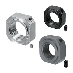
Bearing Lock Nuts
| Product name | Bearing Lock Nuts - Square Type, Coarse Thread |
|---|---|
| Part number | BNGS6 |
* Orange colored cells in the table below indicate the part numbers used in this example.
Selection criteria
Compact nut designed exclusively for tightening the bearings
Available sizes
■Bearing Lock Nuts - Square
| Screw Pitch Type | Material | Hardness | Surface Treatment | Accessory | |
|---|---|---|---|---|---|
| Coarse ・ Fine | 1018 Carbon Steel | - | Black Oxide | Set Piece (Copper Alloy) | Set Screw(4137 Alloy Steel) |
| 1045 Carbon Steel Thermal Refined | 22-28HRC | ||||
| 304 Stainless Steel | - | - | Set Screw(304 Stainless Steel ) | ||
■Sizes and Dimensions
| Thread Dia. x Pitch | Retainer O.D. | External Size | Overall thickness | Set Screw Dia. | |
|---|---|---|---|---|---|
| Coarse Thread | Fine Thread | ||||
| M3×0.5 | M3×0.35 | φ4 | □10 | 5.5 | M3 |
| M4×0.7 | M4×0.5 | φ5 | |||
| M5×0.8 | M5×0.5 | φ9 | □11 | ||
| M6×1.0 | M6×0.75 | φ10 | □12 | ||
| M8×1.25 | M8×1.0 | φ13 | □14 | 6.5 | |
| M10×1.5 | M10×1.0 | φ16 | □17 | 8 | M4 |
| M12×1.75 | M12×1.0 | φ17 | □19 | ||
| - | M15×1.0 | φ21 | □22 | 10 | |
| M16×2.0 | - | ||||
| - | M17×1.0 | ||||
| M20×2.5 | M20×1.0 | φ26 | □30 | 13 | |
| M24×3.0 | - | φ33 | □35 | 15 | M5 |
| - | M25×1.5 | ||||
| M30×3.5 | M30×1.5 | φ39 | □40 | 20 | M6 |
| - | M35×1.5 | φ43 | □45 | ||
| M40×1.5 | φ48 | □49 | 25 | ||
| M50×1.5 | φ61 | □63 | |||

Gussets
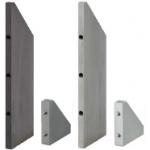
| Product name | Gussets- Tapped Holes, Standard Holes Position, Standard Perpendicularity Type |
|---|---|
| Part number | RBBW30-30-6 |
* Orange colored cells in the table below indicate the part numbers used in this example.
Selection criteria
Economical support.
Available sizes
■Gussets- Tapped Holes, Standard Holes Position, Standard Perpendicularity Type
| Precision Type | Material | Surface Treatment |
|---|---|---|
| Standard Grade (perpendicularity: 0.05/100) ・ Precision Grade (perpendicularity: 0.02/100) | 1018 Carbon Steel | - |
| Black Oxide | ||
| Electroless Nickel Plating | ||
| 5052 Aluminum Alloy | - | |
| Clear Anodize | ||
| Black Anodize | ||
| 304 Stainless Steel | - |
Sizes and Dimensions
| Precision Type | Short side | Long side | Thickness/Tapped Hole Dia. | Tapped Hole Depth | ||||||||||||
|---|---|---|---|---|---|---|---|---|---|---|---|---|---|---|---|---|
| 30 | 40 | 50 | 60 | 80 | 100 | SS400・SUS304 | 5052 Aluminum Alloy | |||||||||
| t6 | t9 | t12 | t16 | t6 | t10 | t12 | t16 | |||||||||
| Standard Grade (perpendicularity: 0.05/100) ・ Precision Grade (perpendicularity: 0.02/100) | 20 | ○ | ○ | ○ | ○ | ○ | M3 | M3 | Diameter×1.5 | |||||||
| 30 | ○ | M3 | M6 | M3 | M6 | |||||||||||
| ○ | ○ | ○ | ○ | ○ | M5 | M6 | M5 | M6 | ||||||||
| 40 | ○ | ○ | ○ | ○ | ○ | M5 | M6 | M5 | M6 | |||||||
| M6 | M8 | M6 | M8 | |||||||||||||
| 50 | ○ | ○ | ○ | ○ | M5 | M6 | M5 | M6 | ||||||||
| M6 | M8 | M6 | M8 | |||||||||||||
| 60 | ○ | ○ | ○ | M5 | M6 | M5 | M6 | |||||||||
| M6 | M8 | M6 | M8 | |||||||||||||
| 80 | ○ | ○ | M5 | M6 | M8 | M5 | M6 | M8 | ||||||||
| M6 | M8 | M6 | M8 | |||||||||||||
| 100 | ○ | M5 | M6 | M8 | M5 | M6 | M8 | |||||||||
| M6 | M8 | M6 | M8 | |||||||||||||


-
 Terms of use of CAD data and simplified drawing data
- These terms and conditions (hereinafter referred to as “the Terms") set forth the conditions for downloading CAD data and simplified drawing data posted on https://vn.misumi-ec.com/ (hereinafter referred to as the "Website") operated by MISUMI VIETNAM CO.,LTD. (hereinafter referred to as "MISUMI"). By downloading CAD data and simplified drawing data posted on the Website (hereafter referred to as “Data”), customers are deemed to have agreed to these Terms.
- 1. Purpose of Use
-
MISUMI offers the following:
1)CAD data found on the Website (3D CAD data, 3D Intermediate data and 2D CAD data) for the purpose of informing customers of the characteristics of the products offered by MISUMI or a manufacturer affiliated with MISUMI for use in their designs.
2)Simplified drawing data (in PDF format) for the purpose of checking the specifications of products. - 2. Characteristics of Data
- There may be a discrepancy in certain characteristics of products (for example: tolerance, surface roughness, chamfer, etc.) between the Data and the actual product. Furthermore, for the purpose of reducing the file size of the Data, some information such as oil groove shapes, threads, or spring shapes, may be removed from the Data.
- 3. Disclaimer
- MISUMI carefully creates the Data but makes no warranty as to the accuracy of the Data. MISUMI may at any time, and with no prior notice to customers, revise or delete Data. MISUMI assumes no responsibility for any damage or loss resulting from any revision or deletion of the Data, or any errors in said data. Customers are solely responsible for all aspects of their own designs, including those made using MISUMI’s CAD data. MISUMI may provide customers with design example data on the Website, but the quality, accuracy, functionality, safety, reliability, etc., of such data are not guaranteed. MISUMI may, at any time, and in its sole discretion, request that the customer cease its use of or destroy the Data in its possession. MISUMI may request the customer provide MISUMI documentation of such destruction.
- 4.Prohibited Acts
-
Customers or users of the Data, are prohibited from the following acts regarding the Data, in whole or in part:
(1)Requesting quotations or placing orders for products with third parties other than those authorized by MISUMI or its affiliates;
(2)Receiving quotations or orders for products from third parties by providing the Data to a third party or using the Data in their own business;
(3)Displaying links to the Website related to the Data on their own websites, etc., without MISUMI's consent;
(4)Using or reproducing the Data beyond the scope of the above-stated Purpose of Use;
(5)Modifying, altering, tampering with, translating, or adapting the Data;
(6)Selling, transferring, lending, sublicensing, or providing the Data to third parties in any way without MISUMI’s consent;
(7)Altering the content, reverse engineering, decompiling, disassembling, or analyzing the Data;
(8)Publicly disclosing or exhibiting the Data without MISUMI's consent;
(9)Using the Data for the purpose of providing products and services identical or similar to those of MISUMI;
(10)Performing acts that interfere with the proper functioning of this Website, such as acquiring Data in bulk. - 5. Copyright
-
All title and copyright in and to any information contained in the Data are owned by MISUMI or the relevant manufacturer affiliated with MISUMI and are protected by applicable copyright laws and international treaties. By downloading Data, the customer acquires no ownership rights of any kind in the intellectual property contained within. Without prior approval from MISUMI, no part of the Data may be utilized (reproduced, modified, reverse-engineered, uploaded, presented, sent, distributed, licensed, sold, or published) for any purpose other than that mentioned above.
In the event Data is found to have been to be used for any purpose other than that mentioned above or against any applicable laws, MISUMI may pursue any legal remedy available to it, which may result in forbidding the offending user from using the Data or accessing the Website. - 6. Third-Party Data
- MISUMI offers some Data provided by third parties. Such Data may be subject to separate terms and conditions, in addition to these terms. MISUMI makes no guarantee or warranty regarding Data from third parties.
- 7. Export Control
- Customers shall comply with all applicable laws and regulations regarding the export of the Data.
- 8. Amendments to the Terms
- MISUMI may, at any time, and in its sole discretion, modify these terms and conditions; any such modification will be effective immediately.
- 9. Severability
- If any term or provision of these Terms is invalid, illegal, or unenforceable in any jurisdiction, such invalidity, illegality, or unenforceability shall not affect any other term or provision of these Terms or invalidate or render unenforceable such term or provision in any other jurisdiction.
- 10.Miscellaneous
- These Terms and any disputes arising in connection therewith shall be exclusively governed by and construed in accordance with the with the laws of Vietnam without regard to its conflicts of law principles. Any dispute arising out of or in relation with these Terms and Conditions shall be resolved by arbitration at the Vietnam International Arbitration Centre (VIAC) in accordance with its Rules of Arbitration. The place of arbitration shall be Hanoi and the language to be used in the arbitral proceedings shall be English.
- Revised:16th November, 2025
CAD Download (Unit Assembly)
CAD Download: File Format
CAD Data Limitations
-
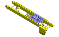
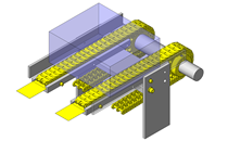
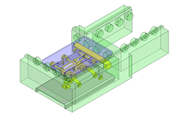
Assembly data shows the assembly drawings in the concept design phase. The sole purpose of the data is to explain the structure and functionality of the assembly and is not considered nor to be used as a final design.
You will need to edit the Data so that it meets your specific design conditions. -
Unit assembly Data consists of some sub-assemblies.
It is configured so that each sub-assembly unit can be used as it is or edited. - The Data for fabricated parts is based on easy-to-edit dimensions and shapes in sketches and histories.
- The Data including the third-part components are made by the Company.
* The part in the frame is a sub-assembly unit.
-

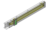
- * Unit assembly Data consists of some sub-assemblies.
It is configured so that each sub-assembly unit can be used as it is or edited.
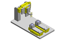
Application Overview
Purpose
- Purpose
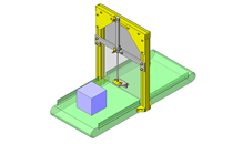
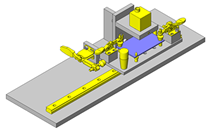
- Reducing the thrust load to the motor shaft without using coupling.
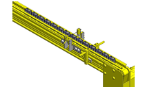
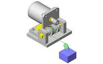
- Operation
- Worm gear is directly mounted on motors shaft, using wire it powers wire drum that lowers and lifts the workpiece.
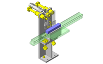
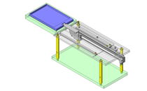
Points for use
- Applicable to thrust load from one direction only.
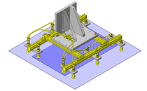
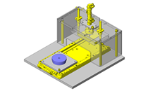
Target workpiece
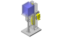
- Shape: Block
- Size: W40 x D40 x H25mm
- Weight: 0.3kg
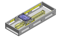
Design Specifications
Operating Conditions or Design Requirements
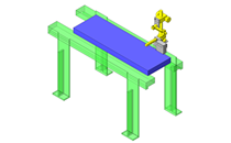
- Up and down stroke: 30mm
- External size: W123 x D125 x H92mm
Required Performance
- Load: 3N
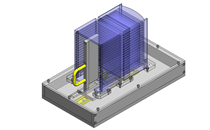
Selection Criteria for Main Components
- A motor with thrust load of 0.8N is selected to pull up a workpiece of 0.3kg.
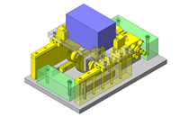
Design Evaluation
Verification of main components
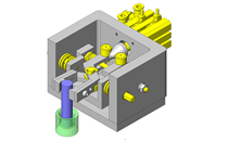
- Select the bearing to withstand the load weight.
- Thrust bearing selection
- Conditional values: Diameter of the wire winding part of the drum d1 = 28mm, pitch circle diameter of the worm wheel d2 = 30mm, motor rotational speed z1 = 1200rpm, workpiece mass W = 0.3kg, gravitational acceleration g = 9.8m/s2, work movement length l1 = 30mm, friction coefficient on the tooth surface μ = 0.0167, tooth rectangular pressure angle a = 20°, worm gear advance angle y1 = 3.58°, pitch circle diameter of worm gear d3 = 16mm, worm gear rotational speed q1 = 1200mm, basic load rating of thrust bearing c1 = 6.8kN
- Number of revolution necessary for the drum to wind the workpiece n1 is given as follows:
n1 = d1 x π/l1 = 28 x π/30 = 2.93
Motor rotation time at that time is given by
t1 = d2 x n1 x (60 x z1) = 30 x 2.93 x (60 x 1200) = 4.40t - Net power H1 applied to the worm gear is given by
H1 = W x g x l1/t1 = 0.3 x 9.8 x 30/4.40 = 0.02N = 2.72 x 10 -5 PS - Apparent friction angle on the tooth surface p1 is given by
p1 = tan-1(μ) = tan-1(0.0167) = 0.957° - Axial thrust load F1 of the worm gear is given by
F1=F2/tan(y+p)=1.432×H1×10 6 /{tan(y1+p1)×d3×q1}×g
=1.432×2.72×10 -5 ×10 6 /{tan(3.58+0.957)×16×1200}×9.8
=0.25N<6.8kN=c1
⇒No problem
Other Design Consideration
- From smoother motion select ball bearings to support shaft drum not oil free bushing even if its a low speed application.
- Avoid any gap/clearance between motor brackets, thrust bearing and worm gear.
Explore Similar Application Examples
Page
-
/
-

-

-
-
-

-

-

-

-

-
-
-

-

-
-

-

-

-
-

-

Relevant category
-

-
-

-

-

-

-

-

-

-

-

-
-
-
-

-

-

-
-

-

-
-

-

-
-

-

-

-
-
-

-

-

-

-

-

Relevant category
-

-

-

-
-

-

-

-

-
-

-

-

-
-
-

-

-
-

-

-

-

-

-

-
-

-

-
-

-
-

-

-

-
-

-
-

-

-

-
-

-

-
-
-
-
-

-

-

-

-

-


