(!) Since support from Microsoft will end on January 14th, 2020, Windows 7 will be excluded from the recommended environment from December 15th, 2019 on this site. Vì lý do Microsoft kết thúc hỗ trợ cho Windows 7 vào ngày 14/01/2020, Windows 7 sẽ là hệ điều hành không được khuyến khích sử dụng với trang web này từ ngày 15/12/2019.
กำลังโหลด...
Over 300 design application ideas
collected from dozens of industries!
Log in to download free CAD models.
Download CAD for the entire application example!
Click the Good IDEA! Button when you like an application example!
*Can only be clicked once per application example.
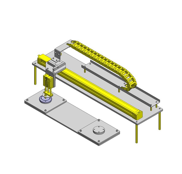
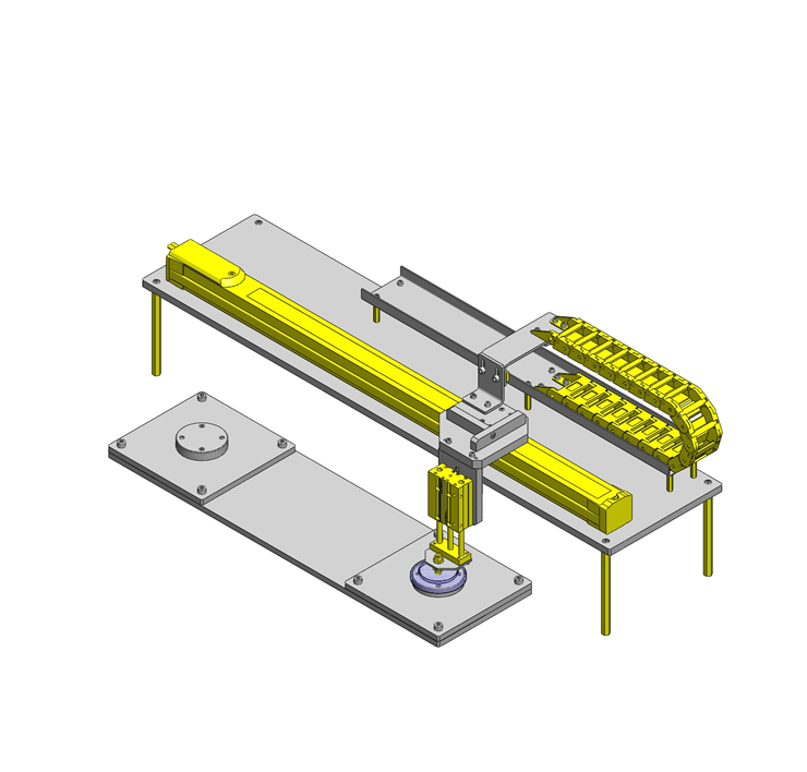
A pick and place mechanism with a single axis robot
Product name | Cylinders with Twin Guides |
---|---|
Part number | MGCLB16-50 |
Features | Cylinders having the guides on both ends for usability. |
For ease of design this was selected for as it is a complete assembly with no extra designing required.
■Cylinder with guides (Fixed stroke type)
Tube I.D. | Bearing | Slide bearing | Linear bushing bearing | Cylinder width | Overall length (Shown + Stroke) | Thickness | ||||||||||||||
---|---|---|---|---|---|---|---|---|---|---|---|---|---|---|---|---|---|---|---|---|
St | 10 | 20 | 25 | 30 | 40 | 50 | 75 | 100 | 10 | 20 | 25 | 30 | 40 | 50 | 75 | 100 | ||||
φ12 | ○ | ○ | - | ○ | ○ | ○ | ○ | ○ | ○ | ○ | - | ○ | ○ | ○ | ○ | ○ | 56 | 39 | 22 | |
φ16 | ○ | ○ | - | ○ | ○ | ○ | ○ | ○ | ○ | ○ | - | ○ | ○ | ○ | ○ | ○ | 62 | 43 | 25 | |
φ20 | - | ○ | - | ○ | ○ | ○ | ○ | ○ | - | ○ | - | ○ | ○ | ○ | ○ | ○ | 72 | 47 | 30 | |
φ25 | - | ○ | - | ○ | ○ | ○ | ○ | ○ | - | ○ | - | ○ | ○ | ○ | ○ | ○ | 86 | 47.5 | 38 | |
φ32 | - | - | ○ | - | - | ○ | ○ | ○ | - | - | ○ | - | - | ○ | ○ | ○ | 112 | 48 | ||
φ50 | - | - | ○ | - | - | ○ | - | ○ | - | - | - | - | - | - | - | - | 146 | 72 | 60 |
*Sensor sold separately
■Non-rotating accuracy of a cylinder
Non-rotational accuracy: Play in between the guide rod and the bearing is represented as the runout angle centered around the piston rod.
Tube I.D. | Non-rotating accuracy of the tip link bar | |
---|---|---|
Slide bearing | Linear bushing bearing | |
φ12 | ±0.12° | ±0.06° |
φ16 | ±0.10° | ±0.06° |
φ20 | ±0.09° | ±0.05° |
φ25 | ±0.08° | ±0.05° |
φ32 | ±0.06° | ±0.04° |
φ50 | ±0.05° | - |
■Cylinder with guides operational pressure range
Min. operating pressure (Mpa): 0.1
Max. operating pressure (Mpa): 1.0
Proof pressure(MPa): 1.5
■Theoretical thrust
(N)
Tube I.D. | Operation direction | Operating pressure (MPa) | |
---|---|---|---|
0.4 | 0.5 | ||
φ12 | Push | 45 | 57 |
Pull | 34 | 42 | |
φ16 | Push | 80 | 101 |
Pull | 60 | 75 | |
φ20 | Push | 126 | 157 |
Pull | 94 | 118 | |
φ25 | Push | 196 | 245 |
Pull | 151 | 189 | |
φ32 | Push | 322 | 402 |
Pull | 241 | 302 | |
φ50 | Push | 785 | 982 |
Pull | 660 | 825 |
■Allowable rotational torque
Indicates allowable dynamic value when the cylinder is operated while a rotational torque is applied at the tip of the guide rod.
(N・m)
Tube I.D. | Bearing type | Stroke | |||||||
---|---|---|---|---|---|---|---|---|---|
10 | 20 | 25 | 30 | 40 | 50 | 75 | 100 | ||
φ12 | Slide bearing | 0.50 | 0.40 | - | 0.33 | 0.28 | 0.25 | 0.77 | 0.65 |
Linear bushing | 0.41 | 0.31 | - | 0.25 | 0.69 | 0.59 | 0.40 | 0.32 | |
φ16 | Slide bearing | 0.91 | 0.75 | - | 0.64 | 0.56 | 0.49 | 1.25 | 1.06 |
Linear bushing | 0.76 | 0.60 | - | 0.49 | 1.14 | 1.02 | 0.79 | 0.65 | |
φ20 | Slide bearing | - | 1.43 | - | 1.23 | 1.08 | 0.96 | 1.51 | 1.27 |
Linear bushing | - | 1.12 | - | 0.93 | 2.12 | 1.90 | 1.50 | 1.24 | |
φ25 | Slide bearing | - | 2.26 | - | 1.94 | 1.71 | 1.52 | 2.38 | 2.00 |
Linear bushing | - | 1.98 | - | 1.65 | 3.75 | 3.37 | 2.68 | 2.22 | |
φ32 | Slide bearing | - | - | 6.71 | - | - | 5.24 | 4.30 | 3.64 |
Linear bushing | - | - | 3.61 | - | - | 2.55 | 6.48 | 5.41 | |
φ50 | Slide bearing | - | - | 13.0 | - | - | 10.8 | - | 10.6 |
■ Allowable lateral load
Indicates allowable dynamic value when the cylinder is operated while a lateral load (load perpendicular to the guide rod) is applied at the tip of the guide rod.
(N)
Tube I.D. | Bearing type | Stroke | |||||||
---|---|---|---|---|---|---|---|---|---|
10 | 20 | 25 | 30 | 40 | 50 | 75 | 100 | ||
φ12 | Slide bearing | 24 | 19 | - | 16 | 14 | 12 | 37 | 31 |
Linear bushing | 20 | 15 | - | 12 | 33 | 29 | 19 | 16 | |
φ16 | Slide bearing | 40 | 33 | - | 28 | 24 | 21 | 55 | 46 |
Linear bushing | 33 | 26 | - | 21 | 50 | 44 | 34 | 28 | |
φ20 | Slide bearing | - | 52 | - | 45 | 39 | 35 | 55 | 46 |
Linear bushing | - | 41 | - | 34 | 77 | 69 | 54 | 45 | |
φ25 | Slide bearing | - | 69 | - | 60 | 52 | 47 | 73 | 62 |
Linear bushing | - | 61 | - | 51 | 115 | 104 | 82 | 68 | |
φ32 | Slide bearing | - | - | 166 | - | - | 131 | 107 | 91 |
Linear bushing | - | - | 90 | - | - | 34 | 162 | 135 | |
φ50 | Slide bearing | - | - | 296 | - | - | 245 | - | 241 |
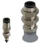
Product name | Suction Cups - with Fitting, Spring Type, Shape K |
---|---|
Part number | MVPKN10 |
Suitable for gripping the flat surface of the workpiece
Loss of suction ability due to wear and degradation
■Suction cup with fitting (With pad) Fixed type, Top tube connection: One touch type (Shape K)
Body material | Surface treatment | Pad shape | Pad material |
---|---|---|---|
Brass | Electroless nickel plating | Standard | Nitrile rubber |
Conductive silicon rubber | |||
Fluorine rubber | |||
Deep type | Nitrile rubber | ||
Fluorine rubber |
■Sizes and Dimensions
Pad shape | Suction pad | Port size | Overall length | Mounting thread DIA. x Pitch | |
---|---|---|---|---|---|
O.D. | Length | ||||
Standard | φ2 | 4 | φ4 | 28.3 | M6×0.75 |
φ3 | |||||
φ4 | |||||
φ6 | 7 | φ6 | 32.6 | M10×1.0 | |
φ8 | 5.5 | 31.1 | |||
φ10 | 8 | 34.1 | M12×1.0 | ||
φ15 | 9 | 35.1 | |||
φ20 | 10 | 37.5 | M14×1.0 | ||
Deep type | φ20 | 11 | 38.7 | ||
φ25 | 12 | 39.7 | |||
φ30 | 14 | 41.7 | |||
φ40 | 17.5 | 45.2 |
Aiming to reduce design steps by structuring the major mechanism with a combination of commercially available components.
Thank you for downloading the data.
Click the Good IDEA! button when you find interesting design tips.
This data is utilized in order to list more useful application examples in the future.
* The part in the frame is a sub-assembly unit.
MISUMI Vietnam Company Limited, Legal Representative: Tomohiro Watanabe,
phone: 0222-361-1555, e-mail: cs@misumi.com.vn, Enterprise Code: 0107514576,
Date of Issuance: 22 July 2016, Place of Issuance: Bac Ninh, Business Certificate No. 6573041568-KD dated 27 September 2016 issued by the People's Committee of Bac Ninh
Công ty TNHH MISUMI Việt Nam, Đại diện theo pháp luật: Tomohiro Watanabe,
Điện thoại: 0222-361-1555, e-mail: cs@misumi.com.vn, Mã số doanh nghiệp: 0107514576,
ngày cấp 22/7/2016, nơi cấp: Bắc Ninh, Giấy phép kinh doanh số: 6573041568-KD ngày cấp 27/9/2016 bởi UBND tỉnh Bắc Ninh
Copyright © MISUMI Corporation All Rights Reserved.