(!)Due to Microsoft's end of support for Internet Explorer 11 on 15/06/2022, this site does not support the recommended environment.
- inCAD Library Home
- > No.000172 Space-Saving Long-Stroke Mechanism
No.000172 Space-Saving Long-Stroke Mechanism
13
13
Speeding up with long stroke.
Relevant category
- * Unit assembly Data consists of some sub-assemblies.
It is configured so that each sub-assembly unit can be used as it is or edited.
Application Overview
Purpose
- Purpose
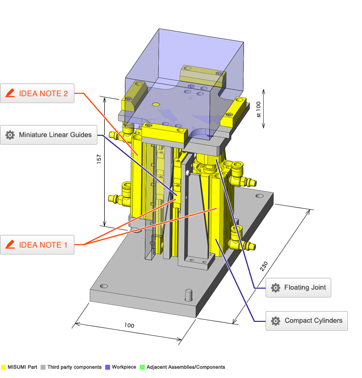
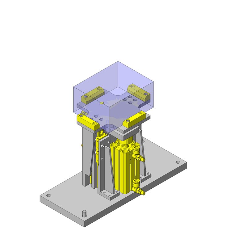
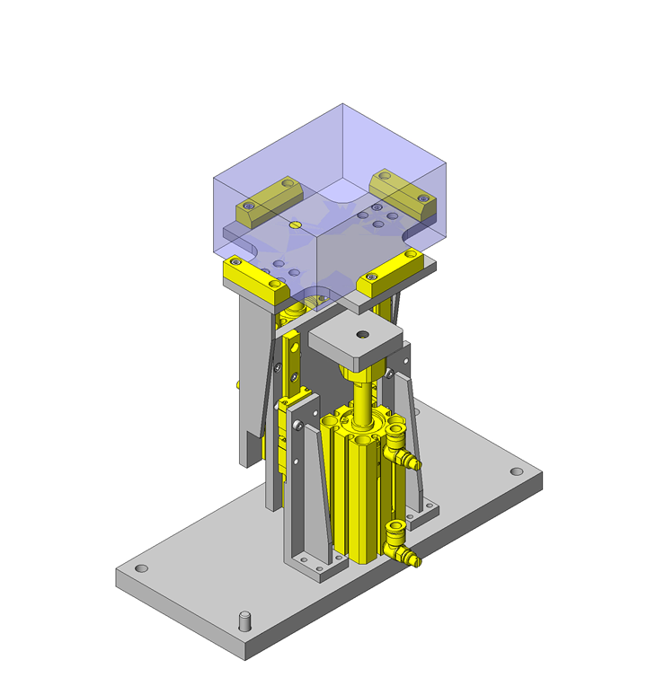
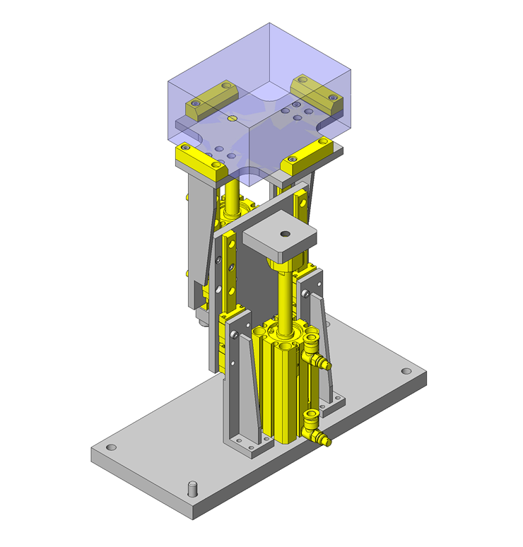
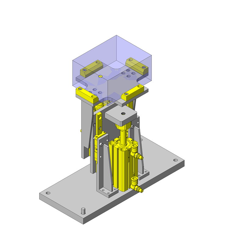
- Provide long stroke vertical motion using two stages of linear guides and air cylinders.
- Operation
- The two stage design allows for longer stroke.
Target workpiece
- Shape: box shape workpiece
- Size: W100 x D80 x H50mm
- Weight:1kg
Design Specifications
Operating Conditions or Design Requirements
- Ascending/descending stroke: 100mm
- Cylinder stroke:50mm
- Tube inner diameter:φ20mm
- Cylinder output:126×70%N(Applied pressure 0.4MPa)
- Outer dimensions:W230×D105×H157(H245 when ascended)mm
Required Performance
- Running parallelism:15×2=30μm
- Allowable Load:60N
Selection Criteria for Main Components
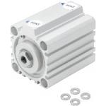
- Air Cylinder
- Stroke of 50mm or longer and output of 30N or above
Design Evaluation
Verification of main components
- A cylinder is selected so that the force required for raising the workpiece is obtained.
- Ascending output
- Conditional value: target workpiece mass: M1 = 1kg, ascending structure mass: M2 = 2kg, ascending stroke: L = 100mm, gravitational acceleration g = 9.8m/s², air pressure: a = 0.4MPa, cylinder load factor: η = 70% = 0.7
- Load applied during ascending:W=W1+W2=M1×g+M2×g=1×9.8+2×9.8=9.8+19.6=29.4N
- Required cylinder thrust:P=W/η=29.4/0.7=42N
⇒A cylinder with a cylinder inner diameter of φ12mm or higher is selected. - Stroke: L = 100mm, stroke required for each cylinder: L' = L/2 = 100/2 = 50mm
⇒A standard cylinder with a stroke of 50mm and an inner diameter is φ20mm is selected. - Based on the thrust of a cylinder with a φ20 inner diameter mm: P', the allowable ascending load: W' is verified.
P'=π/4×20²×0.4=126N
W'=P'×η-W2=126×0.7-19.6=68.6N
⇒Allowable ascending load:W'=68.6N
Other Design Consideration
- Cylinder tube inner diameter will usually increase with stroke.
Linear guide must have length equivalent to stroke.
Explore Similar Application Examples
Page
-
/
-
-
Relevant category


