(!)Due to Microsoft's end of support for Internet Explorer 11 on 15/06/2022, this site does not support the recommended environment.
- inCAD Library Home
- > No.000289 Removal of Static Electricity from Large Workpieces
No.000289 Removal of Static Electricity from Large Workpieces
16
16
Parallel use of two single-axis actuators
Relevant category
- * Unit assembly Data consists of some sub-assemblies.
It is configured so that each sub-assembly unit can be used as it is or edited.
Application Overview
Purpose
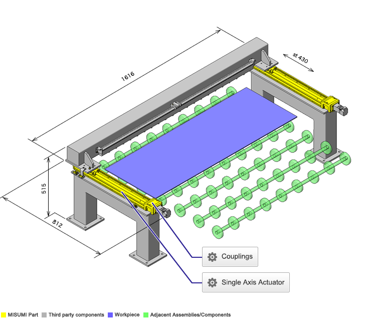
- A device to remove static electricity from resin material that is likely to create an electrical charge.
- Static electricity is removed after the workpiece is stopped.
Points for use
- Automatic horizontal movement enabled by single-axis actuators and servo motors.
Target workpiece
- Workpiece: electrically charged resin material.
- Dimensions: W430 x D1200 x t5mm
- Mass: 3.4kg
Design Specifications
Operating Conditions or Design Requirements
- Operational Specifications
- Action stroke: 430mm
- Feed speed: 45mm/sec
- Dimensions
- Outer dimensions: W1616 x D812 x H515mm
Selection Criteria for Main Components
- Capacity of single-axis actuator.
Design Evaluation
Verification of main components
- The actuator capacity is verified based on the load condition.
- Capacity of single-axis actuator.
-
- Conditional value: stroke Ls = 430mm, feed speed V = 45mm, number of rpms n1 = 2rpm, load factor fw = 1.2 (when AC servo motor is used), operation condition "at low speed (250mm/sec (15m/min) or less)," beam [mass [kg], distances from linear block to the centers of gravity of X, Y, and Z [mm]] = [9.81, 80.18, 750, 50.17], ionizer [mass [kg], distances from linear block to centers of gravity of X, Y, and Z [mm]] = [0.73, 16.88, 750, 42.66]
→ Service life of rail part: 7 [years] * Calculated using Misumi EC Calculation Software.
→ Converted into service period assuming it is used 8 hours a day: 21 [years]
- Conditional value: stroke Ls = 430mm, feed speed V = 45mm, number of rpms n1 = 2rpm, load factor fw = 1.2 (when AC servo motor is used), operation condition "at low speed (250mm/sec (15m/min) or less)," beam [mass [kg], distances from linear block to the centers of gravity of X, Y, and Z [mm]] = [9.81, 80.18, 750, 50.17], ionizer [mass [kg], distances from linear block to centers of gravity of X, Y, and Z [mm]] = [0.73, 16.88, 750, 42.66]
Other Design Consideration
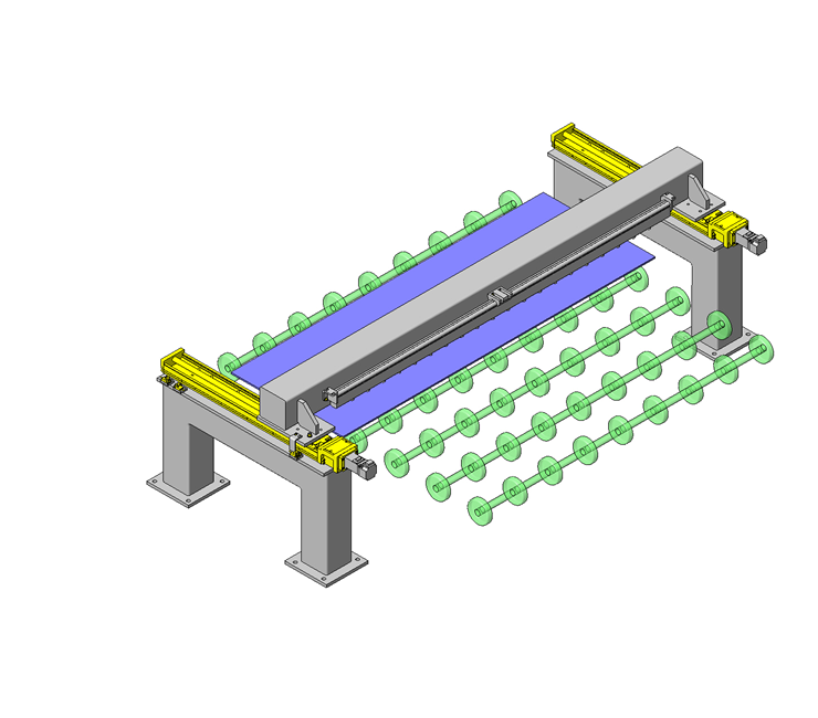
- Due to the large moment load of the removal device, two single-axis actuators are used in parallel.
- Feed mechanism are controlled by servo motors.
- To achieve synchronization, a sequencer and servo amplifier are utilized.
- Calculate the required spacing between the ionizer and the workpiece during the design stage.
- The three photo sensors mounted on the main frame detect overruns at the origin position and both ends.
Explore Similar Application Examples
Page
-
/
-
-
Relevant category
-
Relevant category


