(!) Since support from Microsoft will end on January 14th, 2020, Windows 7 will be excluded from the recommended environment from December 15th, 2019 on this site. Vì lý do Microsoft kết thúc hỗ trợ cho Windows 7 vào ngày 14/01/2020, Windows 7 sẽ là hệ điều hành không được khuyến khích sử dụng với trang web này từ ngày 15/12/2019.
Search by Category / Brand Tìm theo danh mục, nhãn hiệu
Search by Category Tìm theo danh mục
- Scheduled Maintenance Notice: This site will be unavailable due to scheduled maintenance from 8:00 24/11/2024 to 6:00 (ICT) 25/11/2024. We apologize for the inconvenience.
- [Thông báo] Cập nhật địa chỉ kho tập kết hàng hóa tại khu vực miền Nam của MISUMI Việt Nam. Xem chi tiết.
[Announcement] Update on warehouse address in the Southern region of MISUIMI Vietnam. See more. - [Cảnh Báo] Thủ Đoạn Lừa Đảo Từ Nhân Viên Giao Hàng – Yêu Cầu Trả Phí Ship. Xem chi tiết.
[Warning] Fraud Calling from Shipper - Asking to Pay Shipping Fee. See more.
Specification/DimensionsĐặc điểm kỹ thuật / Kích thướcĐặc điểm kỹ thuật / Kích thước
-
Number of Pins
-
CADCAD
- 2D
Days to ShipSố ngày giao hàng
-
- Alltất cả các
- Same day
Specify AlterationsChỉ định thay đổi
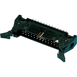
MIL Connector PCB Straight Male Connector (Lever Model) (Part Number)
- Volume Discount
- UL
- MIL
- For Signal
- Solder
- Gold Plated
- Lever Lock
Copy Part Number URL to Clipboard
The part number URL has been copied into your clipboard.-
- Order Qty :
-
-
- Total Price :
- ---
-
- Days to ship :
- ---
Select part number to Order Now/ Add to Cart

● A versatile board connector with board mounting hole pitch of 2.54 mm that allows mounting on commercially available universal boards and the like.
● The direction of the pin is vertical with respect to the board surface.
● Since it has a lock mechanism when coupling, it can securely fix the connectors.
● UL No. E52653

Rated Current: 1A
Rated Voltage: 200V AC

· Please note that 50, 60 and 64-core models are available in 2 models with different polarity slot positions.
· The contact will be the male (pin) model only.
Product Description
[Features]Hirose Electric's lever-type, circuit board mount, MIL straight male connector. A wire-to-wire connector for OMRON KEYENCE PLC. It is a highly versatile circuit board connector that can be mounted on commercially available universal circuit boards, etc., as the circuit board mounting hole pitch is 2.54 mm. The pin direction is vertical to the circuit board surface. Since it has a lock mechanism at the time of connection, the connector can be securely connected and fixed.
Specifications

| Model | Number of Cores | Weight (g) |
| HIF3-6PA-2.54DSA71 | 6 | 3.9 |
| HIF3BD-10PA-2.54DSA71 | 10 | 4.4 |
| HIF3BA-14PA-2.54DSA71 | 14 | 5.0 |
| HIF3BA-16PA-2.54DSA71 | 16 | 5.3 |
| HIF3BA-20PA-2.54DSA71 | 20 | 6.1 |
| HIF3BA-26PA-2.54DSA71 | 26 | 6.9 |
| HIF3BA-30PA-2.54DSA71 | 30 | 7.5 |
| HIF3BA-34PA-2.54DSA71 | 34 | 8.0 |
| HIF3BA-40PA-2.54DSA71 | 40 | 9.2 |
| HIF3BA-50PA-2.54DSA71 | 50 | 10.4 |
| HIF3BB-50PA-2.54DSA71 | 50 | 10.6 |
| HIF3BA-60PA-2.54DSA71 | 60 | 12.0 |
| HIF3BB-60PA-2.54DSA71 | 60 | 12.2 |
| HIF3BA-64PA-2.54DSA71 | 64 | 13.0 |
| HIF3BB-64PA-2.54DSA71 | 64 | 13.0 |
More Information


| Part Number |
|---|
| HIF3BA-16PA-2.54DSA71 |
| HIF3BB-60PA-2.54DSA71 |
| Part Number | Price | Minimum Order Qty. | Volume Discount | Days to ShipSố ngày giao hàng | RoHS | Number of Pins |
|---|---|---|---|---|---|---|
56,510 VND | 1 Piece(s) | Same day | 10 | 16 | ||
96,650 VND | 1 Piece(s) | Same day | 10 | 60 |
Loading...Tải…
Connection Method for Pressure Welding Type MIL Socket Connector


Table of Possible Connectors for Pressure Welding
| Product Name | Model |
|---|---|
| D-sub Connector (EMI Pressure Welding Type) |
FD*-*PF05 (Male) FD*-*P05 (Male) FD*-*S05 (Female) |
| Centronics Connector General-purpose Pressure Welding Spring-lock Type |
57F-30***-20S (Male) 57F-40***-20S (Female) |
| Centronics Connector (EMI Pressure Welding Type) |
57FE-30***-20N-D8 (Male) 57FE-40***-20N-D8 (Female) |
| FCN Pressure Welded Connector | FCN-367J***-AU-F (Female) |
| MIL Socket Connector Female Pressure Welding Contact Connector (without Lock) |
HIF3**-**D-2.54R (Female) 79**-B500FL-3448 * Cannot be used for 60 / 64 core type. The type with 2 guide keys also cannot be used |
| MIL Socket Connector Female Pressure Welding Contact Connector (with Lock) |
XG4M-****-U |
Basic InformationThông tin cơ bản
| Connector Shape | Square shape | Connector series initials | M/N/O | M/N/O | MIL |
|---|---|---|---|---|---|
| Applicable pin/contact | Male (plug) | Application | Cable-to-board | Allowable Current(A) | 1 |
| Allowable Voltage(V) | 200 | Wire connection method | Solder | Connection direction | Straight |
| Protection function (environmentally resistant) | None | Representative Standard | UL | Polarity Guide/Slot(Piece) | Central 1 |
| Polarizing key groove/key mount(Piece) | Left and Right Each 1 | Other standards (MIL) | ○ | Removal method | Others |
- The specifications and dimensions of some parts may not be fully covered. For exact details, refer toCác thông số kỹ thuật và kích thước của mã sản phẩm có thể không được bao phủ đầy đủ. Để biết chi tiết chính xác, hãy tham khảo manufacturer catalogsdanh mục nhà sản xuất ..


How can we improve?
How can we improve?
While we are not able to respond directly to comments submitted in this form, the information will be reviewed for future improvement.
Customer Privacy Policy
Thank you for your cooperation.
While we are not able to respond directly to comments submitted in this form, the information will be reviewed for future improvement.
Please use the inquiry form.
Customer Privacy Policy