(!) Since support from Microsoft will end on January 14th, 2020, Windows 7 will be excluded from the recommended environment from December 15th, 2019 on this site. Vì lý do Microsoft kết thúc hỗ trợ cho Windows 7 vào ngày 14/01/2020, Windows 7 sẽ là hệ điều hành không được khuyến khích sử dụng với trang web này từ ngày 15/12/2019.
Search by Category / Brand Tìm theo danh mục, nhãn hiệu
Search by Category Tìm theo danh mục
- [Thông báo] Cập nhật địa chỉ kho tập kết hàng hóa tại khu vực miền Nam của MISUMI Việt Nam. Xem chi tiết.
[Announcement] Update on warehouse address in the Southern region of MISUIMI Vietnam. See more. - [Cảnh Báo] Thủ Đoạn Lừa Đảo Từ Nhân Viên Giao Hàng – Yêu Cầu Trả Phí Ship. Xem chi tiết.
[Warning] Fraud Calling from Shipper - Asking to Pay Shipping Fee. See more.
Specification/DimensionsĐặc điểm kỹ thuật / Kích thướcĐặc điểm kỹ thuật / Kích thước
-
Features
-
type
- GCPS
- GCPSLK
- GCPSRK
- GCPSS
- GCPSSLK
- GCPSSRK
- GCPSSWK
- GCPSWK
-
Shaft Bore Dia. 1 d1 (or d)(Ø)
-
Shaft Bore Dia. 2 d2 (or d)(Ø)
-
O.D.(Ø)
-
Overall Length(mm)
-
Application
- For Servo Motors
- Stepping Motor
-
Allowable Torque Range(N•m)
-
Allowable Torque(N•m)
-
Shaft Bore Shape
-
Shaft Tightening Method
- Fastening Bolt
- Set Screw
-
CADCAD
- 2D
- 3D
Days to ShipSố ngày giao hàng
-
- Alltất cả các
- Same day
- 8 Day(s) or Less
- 10 Day(s) or Less
Specify AlterationsChỉ định thay đổi
Disc Couplings High Flexible, Single Disc (GCPSS20-4-8)


- Until 31/12/2024
- Volume Discount
- All
- Sale Items
Copy Part Number URL to Clipboard
The part number URL has been copied into your clipboard.-
- Order Qty :
-
-
- Total Price :
- ---
-
- Days to ship :
- ---
Select part number to Order Now/ Add to Cart
Product Description
This is an economy item, The price is cheaper than the MISUMI standard product
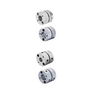
Universal type with excellent flexibility. The price is cheaper than MISUMI diaphragm couplings suitable for servo motors.
Economy High Flexible Single Disc Coupling
- Compact structure with no backlash
- Excellent shock absorption, ensuring no noise and no wear
- High transmission efficiency up to specified percentage
- Suitable for harsh environments and high temperatures
- Simple and lightweight design allows for easy installation and disassembly

![]()
MISUMI Standard
![]()
Cheaper Price
![]()
Product Variety
![]()
3D CAD Support
Coupling Product Overview
The disc Coupling relies on the elastic deformation of the disc to compensate for the relative displacement of the connected two shafts, which is a high-performance flexible Coupling with strong metal components.
It is characterized by compact structure, no backlash, high strength, long service life, no rotation clearance, no influence of temperature and oil pollution, acid resistance, alkali resistance and corrosion resistance.
Applicable motor types: recommended for servo motors, stepping motors and general motors.
Coupling Product Feature
1. Strong ability to compensate for misalignment between two axes. Compared with tooth Coupling, angular displacement can be doubled. In case of radial displacement, reaction force is small, flexibility is large, and certain axial, radial and angular displacements are allowed.
2. It has obvious shock absorption, no noise and no wear.
3. Suitable for working in high temperature (-80+300) and harsh environment, and operate safely under shock and vibration conditions.
4. High transmission efficiency, up to 99.86%. Especially suitable for medium, high speed and high power transmission.
5. Simple structure, light weight, small in size and convenient assembly and disassembly. It can be assembled and disassembled without moving the machine (models with intermediate shaft), and requiring no lubrication.
6. It can accurately transmit the rotational speed without slip, and can be used for transmission of precision machinery.
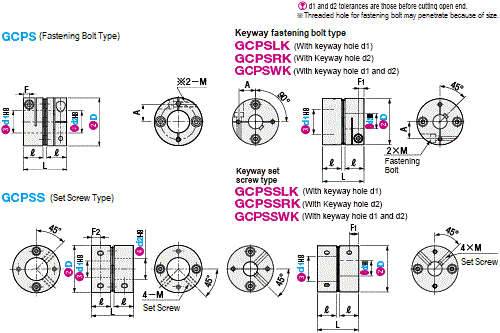
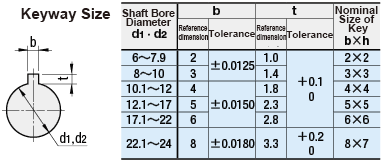
Dimensional Coupling Drawing
 The bolt direction of single disc Coupling is staggered on opposite sides (to improve product balance). The drawings are for reference only. The actual products may differ.
| Type |  Material Material |  Surface Treatment Surface Treatment |  Accessories Accessories | |||
| Body | Disc | Set Screw, Fastening Bolt | Body | Set Screw, Fastening Bolt | ||
| ① | Aluminum | Stainless Steel | SCM435 | Alumite Treatment | Ferroferric Oxide Protective Film | Fastening Bolt |
| ② | Set Screw | |||||
Coupling Specification Table
| D | d1, d2 selection (But d1≤d2) | L | ℓ | F1 | F2 | A | Fastening Bolt | Set Screw | |||||||||||||
| M | Tightening Torque | M | Tightening Torque | ||||||||||||||||||
| (N·m) | (N·m) | ||||||||||||||||||||
| 20 | *4 | *5 | 6 | 6.35 | 8 | 23.05 | 11 | 3.5 | 5.5 | 6.4 | M2.5 | 1.0 | M3 | 0.7 | |||||||
| 26 | *5 | 6 | 6.35 | 8 | 10 | 11 | 25.45 | 11.9 | 3.5 | 5.5 | 9 | ||||||||||
| 29 | *5 | 6 | 6.35 | 8 | 10 | 11 | 12 | 14 | 25.7 | 11.9 | 3.5 | 5.5 | 10.5 | M2.5 | 1.0 | M4 | 1.7 | ||||
| 33 | 6 | 8 | 10 | 11 | 12 | 14 | 15 | 16 | 28.5 | 13 | 4 | 6.5 | 12 | M3 | 1.5 | ||||||
| 39 | 8 | 10 | 11 | 12 | 14 | 15 | 16 | 18 | 35 | 16 | 4.75 | 8 | 14 | M4 | 3.5 | M5 | 4.0 | ||||
 d1, d2*marked products without keyway hole.
■Characteristic Value
| D | Allowable torque (N·m) | Allowable angle (°) | Static torsional rigidity (N·m/rad) | Maximum speed (r/min) | Moment of inertia (kg·m2) | Allowable axial amplitude (mm) | ompensation coefficient | Weight (g) | |
GCPS | GCPSS | ||||||||
| 20 | 1 | 2 | 700 | 10000 | 8.8×10⁻⁷ | ±0.10 | 2 | 16 | 17 |
| 26 | 2 | 1000 | 2.5×10⁻⁶ | ±0.10 | 24 | 26 | |||
| 29 | 3 | 1350 | 4.1×10⁻⁶ | ±0.15 | 31 | 35 | |||
| 33 | 5 | 2000 | 7.7×10⁻⁶ | ±0.20 | 44 | 49 | |||
| 39 | 8 | 4250 | 1.9×10⁻⁵ | ±0.25 | 82 | 88 | |||
 Lateral misalignment is not allowed for single disc type.
 Static torsional stiffness, moment of inertia and weight are the values at the maximum shaft dia..
■Shaft slip torque (N·m)
 When the shaft slip torque is less than the allowable torque, please use it below the shaft slip torque.
| D | d1, d2 | |||||||||||
| 4 | 5 | 6 | 6.35 | 8 | 10 | 11 | 12 | 14 | 15 | 16 | 18 | |
| 20 | 1.0 | 1.0 | 1.0 | 1.0 | 1.0 | - | - | - | - | - | - | - |
| 26 | - | 1.0 | 1.5 | 2.0 | 2.0 | 2.0 | 2.0 | - | - | - | - | - |
| 29 | - | 1.0 | 1.5 | 2.0 | 2.5 | 2.5 | 3.0 | 3.0 | 3.0 | - | - | - |
| 33 | - | - | 2.5 | - | 2.5 | 3.5 | 3.5 | 4.0 | 5.0 | 5.0 | 5.0 | - |
| 39 | - | - | - | - | 5.5 | 8.0 | 8.0 | 8.0 | 8.0 | 8.0 | 8.0 | 8.0 |
Coupling Precautions
1. The Coupling allows axis deviation, and transmits rotation angle and torque, but when the axis deviation exceeds the allowable value, vibration will occur or the service life will be drastically reduced.
Be sure to make calibration and adjustment.
2. Axis deviation includes lateral misalignment (parallel error of two axes), angular misalignment (angular error of two axes) and axial amplitude (axial movement of shaft).
Please calibrate and adjust the shaft to ensure that the axis deviation is below the allowable value recorded in the dimension and performance table of each product.
3. The allowable value of axis deviation recorded in the dimension and performance table refers to the situation when either lateral misalignment, angular misalignment or axial amplitude occurs alone. When more than two axis deviations occur at the same time, the corresponding allowable values are halved respectively.
4. Axis deviation not only occurs when assembling to the device, but also is caused by vibration, thermal expansion and bearing wear in operation. Therefore, it is recommended to set the axis deviation below 1/3 of the allowable value.
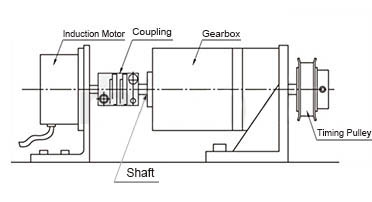
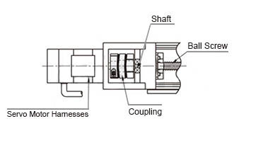
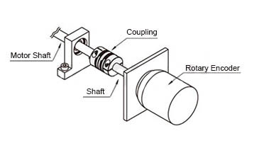
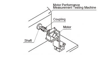
Example of Use Coupling
Coupling Usage Method
STEP1 Insert the Coupling
Confirm that the clamping bolt has been unscrewed, and then remove the dust, foreign matter and oil from the shaft and Coupling bore.
Then, when inserting the Coupling into the shaft, please be careful not to put the disc under excessive stress such as compression or tension.
STEP2 Use fixture to adjust
Please use fixture to adjust and fix the concentricity of the left and right hubs of the Coupling with high accuracy.
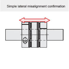
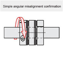
STEP3 Simple lateral misalignment and angular misalignment confirmation
Under the condition of unscrewed bolts, make the Coupling slide axially and confirm its smooth movement.
Then, rotate the Coupling to make sure it moves smoothly.
Lateral misalignment is not allowed for single disc type Coupling, so carry out positioning securely.
STEP4 Installation
Please adjust the shaft insertion amount according to the dimension ℓ in the product catalog, and use a torque wrench to tighten with the specified torque.
* If the specified torque cannot be reached once, please cross fasten the left and right clamps twice or three times.
Part Number
- Incomplete part number.
Please use left hand selections to complete a part number.Incomplete part number.
Please use left hand selections to complete a part number.
| Part Number |
|---|
| GCPSS20-4-8 |
| Part Number | Price | Minimum Order Qty. | Volume Discount | Days to ShipSố ngày giao hàng | Shaft Bore Dia. 1 d1 (or d) (Ø) | Shaft Bore Dia. 2 d2 (or d) (Ø) | O.D. (Ø) | Overall Length (mm) | Application | Allowable Torque Range (N•m) | Features | Allowable Torque (N•m) | Allowable Axial Misalignment (mm) | Moment of Inertia (kg・m2) | Shaft Bore Shape | Shaft Tightening Method |
|---|---|---|---|---|---|---|---|---|---|---|---|---|---|---|---|---|
211,965 VND 190,769 VND | 1 Piece(s) | Available | 10 Day(s) | 4 | 8 | 20 | 23.05 | For Servo Motors | 0.05~1.00 | High Torque Type / Zero Backlash | 1 | 0.1 | 8.8×10⁻⁷ | Standard Bore | Set Screw |
Loading...Tải…
Basic InformationThông tin cơ bản
| Series Name | Disc | Allowable Misalignment | Angular Misalignment / Axial Misalignment | Max. Rotational Speed Range(r/min) | 4001~10000 |
|---|---|---|---|---|---|
| Body Material | Aluminum Alloy | Allowable Angular Misalignment(deg) | 2 | Product Category | Coupling Main Body |
| Max. Rotational Speed(r/min) | 10000 | Disc Material | Stainless Steel | Single/Double | Single |
- The specifications and dimensions of some parts may not be fully covered. For exact details, refer toCác thông số kỹ thuật và kích thước của mã sản phẩm có thể không được bao phủ đầy đủ. Để biết chi tiết chính xác, hãy tham khảo manufacturer catalogsdanh mục nhà sản xuất ..
Frequently asked question (FAQ)FAQ
- Question:Question: What is a coupling?
- Answer:Answer: A coupling is a part that connects two different rotating bodies (motor shaft, ball screw, etc.) and aims at transmitting torque. The load of assembly adjustment is reduced by absorbing the axis deviation (lateral misalignment, angular misalignment and axial amplitude) between rotating bodies. And in case of accidental overload, the coupling is destroyed and the rotating bodies are disconnected to protect the expensive power part and the whole device.
- Question:Question: What are the types of MISUMI couplings?
- Answer:Answer: There are disc type, grooved type, cross type, claw type, bellows type, rigid type and universal joint type.
- Question:Question: How to select coupling according to motor?
- Answer:Answer: Disc type is recommended for servo motors, grooved type is recommended for stepping motors, and cross type is recommended for universal motors.
- Question:Question: How to select according to the purpose, environment, working conditions?
- Answer:Answer: Please refer to the MISUMI website.
- Question:Question: What kind of coupling should be used when the angular misalignment is very large?
- Answer:Answer: Please select the universal joint with allowable angular misalignment of 30 degrees. In addition, when grease cannot be applied regularly, use a rubber sleeve to fill grease and use it.
- Question:Question: Which disc type coupling is better, single disc type or double disc type?
-
Answer:Answer:
Double disc type can absorb angular misalignment and lateral misalignment, but the total length will increase.
Although the total length of the single disc type is short, it is only suitable for applications with narrow space because lateral misalignment is not allowed in the structure. Special attention should be paid to centering during use. - Question:Question: How much is appropriate to insert the shaft into the coupling during installation?
- Answer:Answer: Please select the length of the main body (coupling part) described in the product catalog. If the insertion amount is too short, the shaft may slip and the clamping part may be damaged; If the insertion amount is too long, it will be damaged due to shaft interference inside the coupling.
- Question:Question: Why is it necessary to install a protection cover around the coupling?
- Answer:Answer: Due to high-speed rotation, accidental contact may result in injury or entanglement of gloves, towels, etc. In addition, for some reasons, parts may be damaged or debris may be scattered. Therefore, be sure to install the safety protection cover.
- Question:Question: What should I do if there is no matching shaft bore diameter?
- Answer:Answer: Please select a product with changeable keyway width or available with keyway processing. MISUMI products are divided into MCSLCWK series (disc type), CPOC series (cross type) and MMJN series (claw type), etc.
- Question:Question: Is it a defective product that has difference in groove gap width?
- Answer:Answer: Since the difference is within the dimensional tolerance range, there is no problem.


How can we improve?
How can we improve?
While we are not able to respond directly to comments submitted in this form, the information will be reviewed for future improvement.
Customer Privacy Policy
Thank you for your cooperation.
While we are not able to respond directly to comments submitted in this form, the information will be reviewed for future improvement.
Please use the inquiry form.
Customer Privacy Policy