(!) Since support from Microsoft will end on January 14th, 2020, Windows 7 will be excluded from the recommended environment from December 15th, 2019 on this site. Vì lý do Microsoft kết thúc hỗ trợ cho Windows 7 vào ngày 14/01/2020, Windows 7 sẽ là hệ điều hành không được khuyến khích sử dụng với trang web này từ ngày 15/12/2019.
Search by Category / Brand Tìm theo danh mục, nhãn hiệu
Search by Category Tìm theo danh mục
- [Thông báo] Cập nhật địa chỉ kho tập kết hàng hóa tại khu vực miền Nam của MISUMI Việt Nam. Xem chi tiết.
[Announcement] Update on warehouse address in the Southern region of MISUIMI Vietnam. See more. - [Cảnh Báo] Thủ Đoạn Lừa Đảo Từ Nhân Viên Giao Hàng – Yêu Cầu Trả Phí Ship. Xem chi tiết.
[Warning] Fraud Calling from Shipper - Asking to Pay Shipping Fee. See more.
Specification/DimensionsĐặc điểm kỹ thuật / Kích thướcĐặc điểm kỹ thuật / Kích thước
-
Operating Pressure(MPa)
-
Lead Wire Length(m)
- 0.5
- 1
- 3
- 5
-
Lead Wire Connector
- M8 3‑pin plug connector
- M8 4‑pin plug connector
- M12 4‑pin A cord (normal key) plug connector
- None
-
The number of the switches
- 1
- 2
- 3
- 4
- 5
- 6
- 7
- 8
- 10
- 11
- 12
-
Custom-made
- None
-
Spacer for intermediate fixing
- No spacer
-
Type
- Cylinder
- Stroke adjustment unit
-
Applicable inner diameter of cylinder(ø)
- 20
-
type
- MY-A
- MY1B
-
Type
- Rodless Cylinder
- Others
-
Stroke(mm)
- 1,000
- 1,005
- 1,006
- 1,025
- 1,050
- 1,070
- 1,100
- 1,190
- 1,200
- 1,240
- 1,257
- 1,300
- 1,370
- 1,465
- 1,500
- 1,570
- 1,580
- 1,700
- 1,710
- 1,800
- 1,870
- 1,900
- 2,000
- 2,500
- 3,000
- 50
- 51
- 53
- 55
- 60
- 65
- 67
- 70
- 74
- 75
- 77
- 80
- 81
- 85
- 87
- 88
- 89
- 90
- 97
- 99
- 100
- 101
- 102
- 104
- 105
- 106
- 107
- 108
- 110
- 112
- 113
- 114
- 115
- 116
- 119
- 120
- 121
- 122
- 123
- 124
- 125
- 126
- 127
- 128
- 129
- 130
- 132
- 133
- 134
- 135
- 136
- 137
- 138
- 140
- 144
- 145
- 146
- 150
- 152
- 153
- 154
- 155
- 158
- 160
- 164
- 165
- 166
- 167
- 168
- 169
- 170
- 173
- 175
- 176
- 180
- 181
- 184
- 185
- 186
- 187
- 190
- 191
- 193
- 195
- 196
- 200
- 201
- 202
- 204
- 205
- 206
- 207
- 210
- 213
- 215
- 216
- 220
- 225
- 228
- 230
- 235
- 237
- 240
- 244
- 245
- 246
- 250
- 252
- 253
- 254
- 255
- 256
- 258
- 260
- 263
- 264
- 265
- 266
- 270
- 271
- 274
- 275
- 279
- 280
- 282
- 284
- 285
- 286
- 290
- 295
- 298
- 300
- 301
- 302
- 305
- 306
- 307
- 310
- 311
- 315
- 317
- 318
- 320
- 325
- 326
- 327
- 330
- 331
- 334
- 335
- 340
- 345
- 346
- 349
- 350
- 351
- 352
- 354
- 355
- 357
- 358
- 360
- 363
- 365
- 370
- 371
- 372
- 373
- 375
- 377
- 380
- 381
- 385
- 386
- 387
- 388
- 390
- 392
- 395
- 400
- 405
- 408
- 410
- 415
- 416
- 418
- 420
- 425
- 426
- 430
- 433
- 435
- 438
- 440
- 441
- 445
- 449
- 450
- 452
- 453
- 454
- 455
- 456
- 458
- 460
- 462
- 463
- 465
- 467
- 470
- 473
- 475
- 480
- 485
- 490
- 495
- 500
- 505
- 506
- 507
- 508
- 510
- 513
- 515
- 520
- 522
- 525
- 528
- 530
- 533
- 534
- 535
- 536
- 538
- 540
- 545
- 550
- 554
- 555
- 560
- 561
- 565
- 570
- 572
- 574
- 575
- 580
- 582
- 584
- 585
- 590
- 591
- 593
- 595
- 597
- 600
- 602
- 604
- 605
- 610
- 615
- 620
- 622
- 625
- 627
- 628
- 630
- 634
- 635
- 640
- 641
- 645
- 650
- 655
- 656
- 660
- 663
- 664
- 665
- 669
- 670
- 675
- 677
- 680
- 682
- 685
- 686
- 687
- 689
- 690
- 691
- 692
- 700
- 705
- 710
- 711
- 715
- 718
- 720
- 725
- 730
- 735
- 740
- 745
- 749
- 750
- 753
- 755
- 758
- 760
- 762
- 765
- 766
- 770
- 775
- 780
- 785
- 790
- 795
- 800
- 805
- 810
- 813
- 815
- 816
- 820
- 822
- 825
- 830
- 832
- 835
- 838
- 840
- 842
- 844
- 845
- 850
- 852
- 855
- 860
- 863
- 865
- 870
- 875
- 880
- 885
- 890
- 896
- 900
- 905
- 910
- 915
- 920
- 925
- 930
- 935
- 936
- 940
- 941
- 945
- 946
- 950
- 955
- 960
- 961
- 964
- 965
- 970
- 975
- 977
- 980
- 983
- 985
- 986
- 990
- 1008
- 1010
- 1015
- 1016
- 1020
- 1030
- 1035
- 1040
- 1045
- 1055
- 1060
- 1065
- 1071
- 1075
- 1080
- 1085
- 1090
- 1095
- 1110
- 1114
- 1115
- 1118
- 1120
- 1125
- 1130
- 1133
- 1135
- 1136
- 1137
- 1140
- 1143
- 1150
- 1155
- 1160
- 1170
- 1175
- 1180
- 1210
- 1215
- 1219
- 1220
- 1225
- 1226
- 1230
- 1235
- 1245
- 1250
- 1252
- 1255
- 1260
- 1265
- 1270
- 1275
- 1280
- 1281
- 1283
- 1284
- 1290
- 1291
- 1305
- 1310
- 1315
- 1320
- 1325
- 1330
- 1335
- 1336
- 1340
- 1350
- 1355
- 1360
- 1365
- 1372
- 1375
- 1385
- 1390
- 1398
- 1400
- 1405
- 1410
- 1420
- 1425
- 1430
- 1435
- 1440
- 1450
- 1455
- 1460
- 1470
- 1475
- 1480
- 1490
- 1501
- 1505
- 1510
- 1520
- 1522
- 1524
- 1525
- 1530
- 1536
- 1540
- 1545
- 1550
- 1575
- 1576
- 1585
- 1590
- 1591
- 1600
- 1610
- 1620
- 1625
- 1626
- 1628
- 1630
- 1632
- 1640
- 1646
- 1650
- 1654
- 1660
- 1665
- 1670
- 1675
- 1676
- 1678
- 1680
- 1685
- 1690
- 1702
- 1705
- 1715
- 1720
- 1725
- 1730
- 1740
- 1742
- 1750
- 1753
- 1755
- 1759
- 1760
- 1770
- 1775
- 1778
- 1780
- 1788
- 1805
- 1810
- 1818
- 1820
- 1825
- 1829
- 1830
- 1840
- 1845
- 1850
- 1855
- 1860
- 1865
- 1875
- 1880
- 1885
- 1888
- 1890
- 1898
- 1905
- 1910
- 1920
- 1925
- 1930
- 1935
- 1950
- 1956
- 1959
- 1970
- 1975
- 1977
- 1988
- 1990
- 1998
- 2200
- 2300
- 2400
- 2700
- 3200
- 3400
- 3500
- 4400
-
Table Material
- Aluminum
- Aluminum
-
Max. Load Mass (Horizontal Mounting)(kg)
-
Max. Load Mass(kg)
-
Table Size: Length L(mm)
-
Cylinder I.D.(Ø)
-
Rodless Cylinder Joint Type
- Mechanically Jointed
-
Environment
- General Purpose
-
Table Surface Treatment
- Anodize
- Anodize
-
Guide Type
- Guideless
- Guideless
-
Table Size: Width W(mm)
-
Table Size: Height H(mm)
-
Piping Format
- Centralized piping type
- Standard type
-
Port Screw Type
-
Cushion
-
Specifications
- Magnet built-in
-
Auto Switches
-
Custom-made Specifications
-
Stroke adjustment unit symbol
-
Made-to-order
- Dust seal band NBR lining specifications
- Helical coil insert thread specification
- Long-stroke type
- None
- Shock absorber / soft-type RJ Series mounted cylinder
-
CADCAD
- 2D
- 3D
Days to ShipSố ngày giao hàng
-
- Alltất cả các
- 4 Day(s) or Less
- 31 Day(s) or Less
- 32 Day(s) or Less
- 35 Day(s) or Less
- 37 Day(s) or Less
Specify AlterationsChỉ định thay đổi
Mechanically Jointed Rodless Cylinder, Basic Type, MY1B Series (MY1B10G-1000H)

Copy Part Number URL to Clipboard
The part number URL has been copied into your clipboard.-
- Order Qty :
-
-
- Price :
- ---
-
- Total Price :
- ---
-
- Days to ship :
- ---
Select part number to Order Now/ Add to Cart
(i)
Caution
thận trọng
- Refer to the catalog for product specifications.
- Product pictures are representations. CAD data is not supported by some of the model numbers.
Product Description
Air slide table made by SMC
[Features]
· Capable of being used in combination with various guides depending on the conditions
· Simple, space-saving design without any guides
· A wide variety is available from ø10 to ø100
Details of Mechanical Joint Type Rodless Cylinder, Basic Type MY1B Series

Product image of Mechanical Joint Type Rodless Cylinder, Basic Type MY1B Series
Model Number Notation

Model number examples
Specifications of Mechanical Joint Type Rodless Cylinder, Basic Type MY1B Series
| Tube Internal Diameter (mm) | 10 | 16 | 20 | 50 | 63 | 80 | 100 | |
|---|---|---|---|---|---|---|---|---|
| Fluid | Air | |||||||
| Operation Type | Double-acting type | |||||||
| Operating Pressure Range | 0.2 to 0.8 MPa | 0.15 to 0.8 MPa | 0.1 to 0.8 MPa | |||||
| Proof Pressure | 1.2 MPa | |||||||
| Ambient and fluid temperature | 5 to 60°C | |||||||
| Cushioning | Rubber cushion | Air cushion | ||||||
| Lubrication | Not required | |||||||
| Stroke Length Tolerance | 1,000 or less (0~+1.8) 1,001 to 3,000 (0~+2.8) | 2,700 or less (0~+1.8) 2,701 to 5,000 (0~+2.8) | ||||||
| Piping Connection Port Diameter | Front/side port | M5 × 0.8 | Rc 3/8 | RC 1/2 | ||||
| Bottom port | - | ø4 (Port size 4 mm) | ø10 (Port size 10 mm) | ø18 (Port size 18 mm) | ||||
Piston Speed
| Tube Internal Diameter (mm) | 10 | 16 | 20 | 50 to 100 | |
|---|---|---|---|---|---|
| No stroke adjustment unit | 100 to 500 mm/s | 100 to 1,000 mm/s | |||
| Stroke adjustment unit | A unit | 100 to 200 mm/s | 100 to 1,000 mm/s *1) | - | |
| L unit, H unit | 100 to 1,000 mm/s | - | 100 to 1,500 mm/s *2) | - | |
*1) Be aware that if the stroke adjustment allowance with the adjust bolt leveling mount increases, the air cushion capacity will decrease.
Meanwhile, in ranges exceeding the air cushion stroke, the working piston speed will become 100 to 200 mm/s.
*2) The piston speed used for centralized piping is 100 to 1,000 mm/s.
*3) Use at a speed within the range of the absorption capacity. Please refer to the catalog.
Theoretical Output Table
(Unit: N)
| Tube inner diameter (mm) | Piston Area (mm^2) | Operating Pressure (MPa) | ||||||
|---|---|---|---|---|---|---|---|---|
| 0.2 | 0.3 | 0.4 | 0.5 | 0.6 | 0.7 | 0.8 | ||
| 10 | 78 | 15 | 23 | 31 | 39 | 46 | 54 | 62 |
| 16 | 200 | 40 | 60 | 80 | 100 | 120 | 140 | 160 |
| 20 | 314 | 62 | 94 | 125 | 157 | 188 | 219 | 251 |
| 50 | 1,962 | 392 | 588 | 784 | 981 | 1,177 | 1,373 | 1,569 |
| 63 | 3,115 | 623 | 934 | 1,246 | 1,557 | 1,869 | 2,180 | 2,492 |
| 80 | 5,024 | 1,004 | 1,507 | 2,009 | 2,512 | 3,014 | 3,516 | 4,019 |
| 100 | 7,850 | 1,570 | 2,355 | 3,140 | 3,925 | 4,710 | 5,495 | 6,280 |
*) Theoretical output (N) = pressure (MPa) × pressure receiving area (mm^2).
Weight Table
(Unit: kg)
| Tube inner diameter (mm) | Basic weight | Extra weight per 50 strokes | Weight of Moving Parts | Side support Bracket weight (Per pair) | Stroke adjustment unit weight (Per unit) | ||
|---|---|---|---|---|---|---|---|
| A/B type | A unit weight | L unit weight | H unit weight | ||||
| 10 | 0.15 | 0.04 | 0.03 | 0.003 | 0.01 | - | 0.02 |
| 16 | 0.61 | 0.06 | 0.07 | 0.01 | 0.04 | - | - |
| 20 | 1.06 | 0.10 | 0.14 | 0.02 | 0.05 | 0.05 | 0.10 |
| 50 | 7.78 | 0.44 | 1.40 | 0.04 | - | - | - |
| 63 | 13.10 | 0.70 | 2.20 | 0.08 | - | - | - |
| 80 | 20.70 | 1.18 | 4.80 | 0.17 | - | - | - |
| 100 | 35.70 | 1.97 | 8.20 | 0.17 | - | - | - |
Calculation method/example: MY1B20-300 A
- Basic weight: 1.06 kg
- Cylinder Stroke: 300st
- Extra weight: 0.10/50st
- A unit weight: 1.76 kg
1.06 + 0.10 × 300 ÷ 50 + 0.05 × 2 ≒ 2.17 kg
Structural drawing of centralized piping type / MY1B10G

Structural drawing of centralized piping type / MY1B10G
Component parts table of centralized piping type/ MY1B10G

Image 1 for components parts table of centralized piping type / MY1B10G

Image 2 for components parts table of centralized piping type / MY1B10G
Structural drawing of MY1B16, MY1B20, MY1B50 to MY1B100

Structural drawing of MY1B16, MY1B20, MY1B50 to MY1B100
MY1B16, MY1B20, MY1B50 to MY1B100 components

Image 1 for components parts table of MY1B16, MY1B20, MY1B50 to MY1B100 components parts table

Image 2 of MY1B16, MY1B20, MY1B50 to MY1B100 components
Dimensions example of Mechanical Joint Type Rodless Cylinder, Basic Type MY1B Series
Centralized piping type: ø10 (Cylinder inner diameter: 10 mm)
(Units: mm)

Dimensional drawing of MY1B10G-Stroke
Standard type / centralized piping type ø16 (Cylinder inner diameter: 16 mm), ø20 (Cylinder inner diameter: 20 mm)
(Units: mm)

Dimensional drawing of MY1B16□/MY1B20□-Stroke
(Units: mm)

Image 1 of dimensions table for MY1B16□/MY1B1620□
(Units: mm)

Image 2 of dimensional drawing table for MY1B16□/MY1B20

Dimensional drawing of MY1B16□/MY1B20 piping hole for centralized bottom piping (right: Bottom side piping (Applicable O-ring)
(Units: mm)

Image of piping hole dimension table for centralized bottom piping MY1B16□/MY1B20
* Please process the mounting surface with these dimensions.
Standard type / centralized piping type ø50 (Cylinder inner diameter: 50 mm), ø63 (Cylinder inner diameter: 63 mm)

Dimensional drawing of MY1B50□/MY1B63□-Stroke
(Units: mm)

Dimension table image 1 of MY1B50□/MY1B63□
(Units: mm)

Dimension table image 2 of MY1B50□/MY1B63□

Dimensional drawing of piping hole for centralized bottom piping MY1B50□/MY1B63 (right: Bottom side piping (Applicable O-ring)
(Units: mm)

Image of piping hole dimension table for centralized bottom piping of MY1B50□/MY1B63□
* Please process the mounting surface with these dimensions.
Standard type / centralized piping type ø80 (Cylinder inner diameter: 80 mm), ø100 (Cylinder inner diameter: 100 mm)
(Units: mm)

Dimensional drawing of MY1B80□/MY1B100□-Stroke
(Units: mm)

Dimension table image 1 of MY1B80□/MY1B100□
(Units: mm)

Dimension table image 2 of MY1B80□/MY1B100□

Dimensional drawing of MY1B80□/MY1B100□piping hole for centralized bottom piping (right: Bottom side piping (Applicable O-ring)
(Units: mm)

Image of piping hole dimension table for centralized bottom piping MY1B80□/MY1B100□
* Please process the mounting surface with these dimensions.
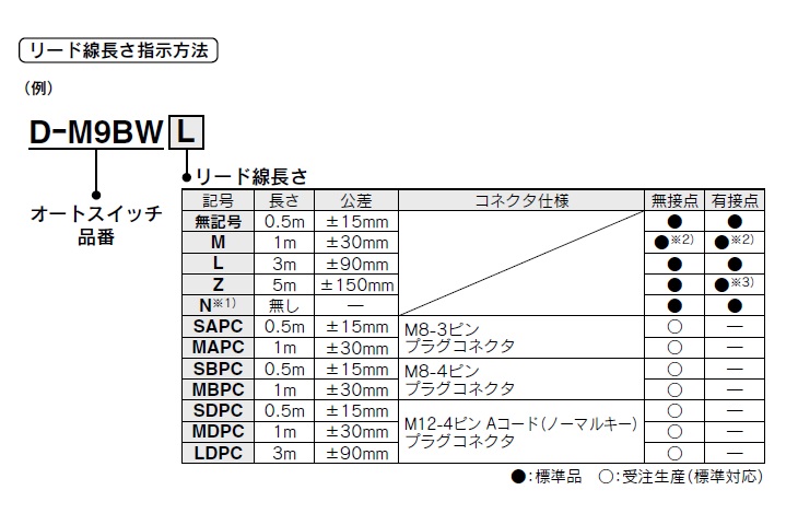
Please refer to the table below for details about lead wire / connector specifications.
| Part Number |
|---|
| MY1B10G-1000H |
| Part Number | Price | Minimum Order Qty. | Volume Discount | Days to ShipSố ngày giao hàng | Type | Stroke (mm) | Table Material | Max. Load Mass (Horizontal Mounting) (kg) | Max. Load Mass (kg) | Table Size: Length L (mm) | Cylinder I.D. (Ø) | Rodless Cylinder Joint Type | Environment | Table Surface Treatment | Guide Type | Table Size: Width W (mm) | Table Size: Height H (mm) | Operating Pressure (MPa) | Piping Format | Port Screw Type | Cushion | Specifications | Auto Switches | Lead Wire Length (m) | Lead Wire Connector | The number of the switches | Custom-made Specifications | Custom-made | Stroke adjustment unit symbol | Made-to-order | Spacer for intermediate fixing | Type | Applicable inner diameter of cylinder (ø) |
|---|---|---|---|---|---|---|---|---|---|---|---|---|---|---|---|---|---|---|---|---|---|---|---|---|---|---|---|---|---|---|---|---|---|
- | 1 Piece(s) | Quote | Rodless Cylinder | 1,000 | [Aluminum] Aluminum Alloy | 5~9.2 | 5 | 50 | 10 | Mechanically Jointed | General Purpose | [Anodize] Hard Anodize | [Guideless] Prototype | 24 | 27 | - | Centralized piping type | M screw | Rubber cushion | Magnet built-in | None | - | - | - | 0.2 to 0.8 | - | H | None | - | - | - |
Loading...Tải…
Please check the type/dimensions/specifications of the part MY1B10G-1000H in the Mechanically Jointed Rodless Cylinder, Basic Type, MY1B Series series.Vui lòng kiểm tra kiểu/kích thước/thông số kỹ thuật của phần MY1B10G-1000H trong chuỗi Mechanically Jointed Rodless Cylinder, Basic Type, MY1B Series.
- The specifications and dimensions of some parts may not be fully covered. For exact details, refer toCác thông số kỹ thuật và kích thước của mã sản phẩm có thể không được bao phủ đầy đủ. Để biết chi tiết chính xác, hãy tham khảo manufacturer catalogsdanh mục nhà sản xuất ..
Products like this...
| Part Number |
|---|
| MY-A16A1 |
| MY-A16A2 |
| MY-A20H1 |
| MY1B10G-1000H-A93 |
| MY1B10G-1000H-M9B |
| MY1B10G-1000H-M9BW |
| Part Number | Standard Unit Price | Minimum order quantity | Volume Discount | Days to ShipSố ngày giao hàng | Type | Stroke (mm) | Table Material | Max. Load Mass (Horizontal Mounting) (kg) | Max. Load Mass (kg) | Table Size: Length L (mm) | Cylinder I.D. (Ø) | Rodless Cylinder Joint Type | Environment | Table Surface Treatment | Guide Type | Table Size: Width W (mm) | Table Size: Height H (mm) | Operating Pressure (MPa) | Piping Format | Port Screw Type | Cushion | Specifications | Auto Switches | Lead Wire Length (m) | Lead Wire Connector | The number of the switches | Custom-made Specifications | Custom-made | Stroke adjustment unit symbol | Made-to-order | Spacer for intermediate fixing | Type | Applicable inner diameter of cylinder (ø) |
|---|---|---|---|---|---|---|---|---|---|---|---|---|---|---|---|---|---|---|---|---|---|---|---|---|---|---|---|---|---|---|---|---|---|
634,000 VND | 1 Piece(s) | 32 Day(s) | Rodless Cylinder | - | - | - | - | - | 16 | Mechanically Jointed | - | - | - | - | - | - | - | - | - | - | - | - | - | - | - | - | - | - | - | - | - | ||
634,000 VND | 1 Piece(s) | 32 Day(s) | Rodless Cylinder | - | - | - | - | - | 16 | Mechanically Jointed | - | - | - | - | - | - | - | - | - | - | - | - | - | - | - | - | - | - | - | - | - | ||
2,081,000 VND | 1 Piece(s) | 32 Day(s) | Rodless Cylinder | - | - | - | - | - | 20 | Mechanically Jointed | - | - | - | - | - | - | - | - | - | - | - | - | - | - | - | - | - | - | - | - | - | ||
- | 1 Piece(s) | Quote | Rodless Cylinder | 1,000 | [Aluminum] Aluminum Alloy | 5~9.2 | 5 | 50 | 10 | Mechanically Jointed | General Purpose | [Anodize] Hard Anodize | [Guideless] Prototype | 24 | 27 | - | Centralized piping type | M screw | Rubber cushion | Magnet built-in | A93 | 0.5 | - | 2 | 0.2 to 0.8 | - | H | None | - | - | - | ||
- | 1 Piece(s) | Quote | Rodless Cylinder | 1,000 | [Aluminum] Aluminum Alloy | 5~9.2 | 5 | 50 | 10 | Mechanically Jointed | General Purpose | [Anodize] Hard Anodize | [Guideless] Prototype | 24 | 27 | - | Centralized piping type | M screw | Rubber cushion | Magnet built-in | M9B | 0.5 | - | 2 | 0.2 to 0.8 | - | H | None | - | - | - | ||
- | 1 Piece(s) | Quote | Rodless Cylinder | 1,000 | [Aluminum] Aluminum Alloy | 5~9.2 | 5 | 50 | 10 | Mechanically Jointed | General Purpose | [Anodize] Hard Anodize | [Guideless] Prototype | 24 | 27 | - | Centralized piping type | M screw | Rubber cushion | Magnet built-in | M9BW | 0.5 | - | 2 | 0.2 to 0.8 | - | H | None | - | - | - |


How can we improve?
How can we improve?
While we are not able to respond directly to comments submitted in this form, the information will be reviewed for future improvement.
Customer Privacy Policy
Thank you for your cooperation.
While we are not able to respond directly to comments submitted in this form, the information will be reviewed for future improvement.
Please use the inquiry form.
Customer Privacy Policy