(!) Since support from Microsoft will end on January 14th, 2020, Windows 7 will be excluded from the recommended environment from December 15th, 2019 on this site. Vì lý do Microsoft kết thúc hỗ trợ cho Windows 7 vào ngày 14/01/2020, Windows 7 sẽ là hệ điều hành không được khuyến khích sử dụng với trang web này từ ngày 15/12/2019.
Search by Category / Brand Tìm theo danh mục, nhãn hiệu
Search by Category Tìm theo danh mục
- MISUMI Việt Nam đồng hành cùng Kỹ sư tương lai trong cuộc thi SMAE Award 2024. Xem chi tiết.
MISUMI Vietnam accompanies Future Engineers in the SMAE Award 2024 competition. See more.
-
 My Components
Thêm v
My Components
Thêm v
-
 Similar ProductsSản phẩm tương tự
 Product Detail
- CAD Data unavailable Dữ liệu CAD không khả dụng
Specification/DimensionsĐặc điểm kỹ thuật / Kích thướcĐặc điểm kỹ thuật / Kích thước
-
轴孔经(加工完毕)d1(Ø)
-
轴孔经(加工完毕)d2(Ø)
-
外径D(Ø)
-
全长L(mm)
-
Allowable Torque(N•m)
-
Allowable Lateral Misalignment(mm)
-
type
- E-LMCPSW
Days to ShipSố ngày giao hàng
-
- Alltất cả các
- 8 Day(s) or Less
- 11 Day(s) or Less
Specify AlterationsChỉ định thay đổi
Double Disc Couplings Set Screw Type

You can add up to 6 items per a category to the compare list.
Brand :
MiSUMi Economy
Part Number :

Copy Part Number URL to Clipboard
The part number URL has been copied into your clipboard.-
- Order Qty :
-
-
- Price :
- ---
-
- Total Price :
- ---
-
- Days to ship :
- ---
Select part number to Order Now/ Add to Cart
- CAD Data unavailable
Product Description
This is an economy item, The price is cheaper than the MISUMI standard product.
Product Overview
Disc coupling is made of several sets of discs (stainless steel sheet) bolted staggered with two coupling halves, each set of discs by several pieces of stacked set.
The disc coupling relies on the elastic deformation of the disc to compensate for the relative displacement of the two shafts connected, is a high-performance flexible coupling with strong metal components.
It is characterized by compact structure, zero backlash, high strength, long service life, no rotating clearance, unaffected by temperature and oil, acid and alkali resistant and corrosion resistant.
Applicable motor types: Recommended for servo motors, stepper motors and general motors.
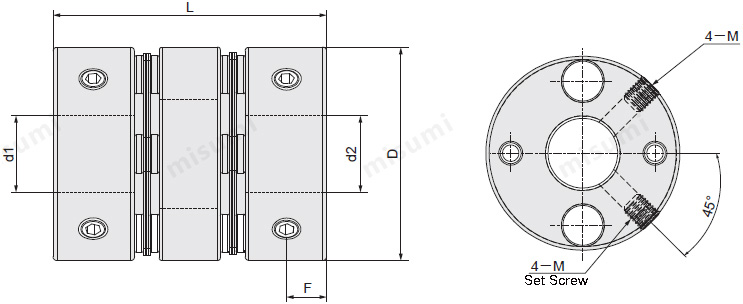
Dimensional Drawing
Set Screw Type
Material table

Material table
| Type | Part |  Material Material |  Surface Treatment Surface Treatment |  Accessory Accessory |
| E-LMCPSW | Hub | Aluminum Alloy | Clear Anodize | Set Screw |
| Screw | Stainless Steel | - |
Specification Table
Please follow the selection steps ~
~ to select the part no. Please specify the shaft hole diameter within the range of d1≤d2.
 ~
~ to select the part no. Please specify the shaft hole diameter within the range of d1≤d2.
Part No.(Type· D) D) | - |  d1 d1 | - | d2 |
| E-LMCPSW26 | - | 5 | - | 10 |
| E-LMCPSW39 | - | 11 | - | 18 |
| Part No. | d1、d2 Shaft Hole Dia.(d1≤d2) | L | ||||||||||||||||||||
| Type | D | |||||||||||||||||||||
| E-LMCPSW | 19 | *3 | *4 | *5 | 6 | 6.35 | 7 | 8 | 27 | |||||||||||||
| 26 | *5 | 6 | 6.35 | 7 | 8 | 9 | 9.525 | 10 | 11 | 12 | 14 | 35 | ||||||||||
| 32 | *5 | 6 | 6.35 | 8 | 9 | 9.525 | 10 | 11 | 12 | 12.7 | 14 | 15 | 41 | |||||||||
| 34 | *5 | 6 | 6.35 | 8 | 9 | 9.525 | 10 | 11 | 12 | 12.7 | 14 | 15 | 16 | 45 | ||||||||
| 39 | 8 | 9 | 9.525 | 10 | 11 | 12 | 12.7 | 14 | 15 | 16 | 17 | 18 | 50 | |||||||||
| 44 | 8 | 9 | 9.525 | 10 | 11 | 12 | 12.7 | 14 | 15 | 16 | 17 | 18 | 19 | 20 | 50 | |||||||
d1, d2* size products without keyway holes.
| Part No. | L | F | Set Screw | Rated Torque (N·m) | Allowable Axial Misalignment (m·m) | Static Torsional Spring Constant (N·m/rad) | Maximum Rotational Speed (r/min) | Compensation Coefficient | Mass (g) | ||
| Type | D | M | Tightening torque N.m | ||||||||
| E-LMCPSW | 19 | 27 | 4.4 | M2.5 | 1.2 | 1 | 0.12 | 700 | 10000 | 1 | 19 |
| 26 | 35 | 5.7 | M4 | 1.7 | 1.5 | 0.15 | 1850 | 10000 | 1 | 29 | |
| 32 | 41 | 6.1 | M4 | 1.7 | 2 | 0.17 | 2850 | 10000 | 1 | 60 | |
| 34 | 45 | 7.1 | M4 | 1.7 | 3 | 0.17 | 4050 | 10000 | 1 | 69 | |
| 39 | 50 | 7.5 | M5 | 4 | 6 | 0.22 | 9000 | 10000 | 1 | 101 | |
| 44 | 50 | 7.5 | M5 | 4 | 9 | 0.22 | 10000 | 10000 | 1 | 190 | |
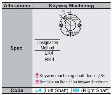
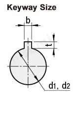
Alterations


| Shaft Hole Dia d1 · d2 | b(Keyway Width) | t Keyway Depth | Keyway Nominal Dim. b X h | |
| LK | RK | |||
| 6 ~ 7.9 | 2 | 2 | 1 | 2x2 |
| 8~10 | 3 | 3 | 1.4 | 3x3 |
| 11~12 | 4 | 4 | 1.8 | 4x4 |
| 13~17 | 5 | 5 | 2.3 | 5x5 |
| 18~22 | 6 | 6 | 2.8 | 6x6 |
Product Features
■Main characteristics of Disc Couplings
1. Strong capability to compensate for misalignment of two shafts, offering twice the angular displacement compared to Jaw couplings, lower reactionary forces during radial displacement, high flexibility, and allows for certain axial, radial, and angular displacements.
2. Provides significant vibration damping effects, operates without noise, and wear-free.
3. Can safely operate under conditions of shock and vibration.
4. High transmission efficiency, up to 99.86%, particularly suitable for medium and high-speed, high-power transmission.
5. Simple structure, lightweight, small volume, and convenient for assembly and disassembly. Installation and removal can be done without moving the machine (refers to the type with an intermediate shaft) and does not require lubrication.
6. Can accurately transmit rotational speed, operates without slip, suitable for the transmission of precision machinery.
Example of Use

Precautions
■Calibration adjustment
1. The coupling allows shaft center deviation and transmits rotation angle and torque. However, when the shaft center deviation exceeds the allowable value, vibration will occur or the service life will be drastically reduced.
2. Axis deviation includes eccentricity (parallel error of two axes), declination (angular error of two axes), and axial amplitude (axial movement of the shaft).
Please calibrate and adjust the shaft to ensure that the axis center deviation is below the allowable value stated in the dimensions and performance table of each product.
3. The allowable value of axial misalignment stated in the dimensions and performance table refers to the situation when one of eccentricity, declination, or axial amplitude occurs alone.
When more than two axis deviations occur at the same time, the corresponding allowable values will be halved respectively.
4. Axial misalignment not only occurs when assembling to the device, but also occurs due to vibration, thermal expansion, bearing wear, etc. during operation. Therefore, it is recommended to set the axis deviation to less than 1/3 of the allowable value.
| Part Number |
|---|
| E-LMCPSW19-[4,5,6,6.35,7,8]-[3,4,5,6,6.35,7,8] |
| E-LMCPSW26-[5,6,6.35,7,8,9,9.525,10,11,12,14]-[5,6,6.35,7,8,9,9.525,10,11,12,14] |
| E-LMCPSW32-[5,6,6.35,8,9,9.525,10,11,12,12.7,14,15]-[5,6,6.35,8,9,9.525,10,11,12,12.7,14,15] |
| E-LMCPSW34-[5,6,6.35,8,9,9.525,10,11,12,12.7,14,15,16]-[5,6,6.35,8,9,9.525,10,11,12,12.7,14,15,16] |
| E-LMCPSW39-[8,9,9.525,10,11,12,12.7,14,15,16,17,18]-[8,9,9.525,10,11,12,12.7,14,15,16,17,18] |
| E-LMCPSW44-[8,9,9.525,10,11,12,12.7,14,15,16,17,18,19,20]-[8,9,9.525,10,11,12,12.7,14,15,16,17,18,19,20] |
| Part Number | Price | Minimum Order Qty. | Volume Discount | Days to ShipSố ngày giao hàng | 轴孔经(加工完毕)d1 (Ø) | 轴孔经(加工完毕)d2 (Ø) | 外径D (Ø) | 全长L (mm) | Allowable Torque (N•m) | Allowable Lateral Misalignment (mm) | Allowable Axial Misalignment (mm) | Moment of Inertia (kg・m2) |
|---|---|---|---|---|---|---|---|---|---|---|---|---|
- | 1 Piece(s) | 11 Day(s) | 5 ~ 8 | 5 ~ 8 | 19 | 27 | 1 | 0.12 | ±0.18 | 8.8x10⁻⁷ | ||
- | 1 Piece(s) | 8 Day(s) | 5 ~ 14 | 5 ~ 14 | 26 | 35 | 1.5 | 0.15 | ±0.30 | 2.8×10⁻⁶ | ||
- | 2 Piece(s) | 8 Day(s) | 5 ~ 15 | 5 ~ 15 | 32 | 41 | 2 | 0.17 | ±0.36 | 7.6×10⁻⁶ | ||
- | 2 Piece(s) | 8 Day(s) | 5 ~ 16 | 5 ~ 16 | 34 | 45 | 3 | 0.17 | ±0.36 | 9.0×10⁻⁶ | ||
- | 2 Piece(s) | 8 Day(s) | 8 ~ 18 | 8 ~ 18 | 39 | 50 | 6 | 0.22 | ±0.45 | 2.7×10⁻⁵ | ||
- | 2 Piece(s) | 8 Day(s) | 8 ~ 20 | 8 ~ 20 | 44 | 50 | 9 | 0.22 | ±0.54 | 4.2×10⁻⁵ |
Loading...Tải…
Basic InformationThông tin cơ bản
| Series Name | Disc | Application | For Servo Motors / Stepping Motor | Features | High Torsional Rigidity / High Torque Type |
|---|---|---|---|---|---|
| Allowable Misalignment | Angular Misalignment / Eccentricity / Axial Misalignment | Body Material | Aluminum Alloy | Allowable Angular Misalignment(deg) | 1.5 |
| Product Category | Coupling Main Body | Max. Rotational Speed(r/min) | 10000 | Disc Material | Stainless Steel |
| Single/Double | Double Disc | Shaft Tightening Method | Set Screw | Shaft Hole Shape | Standard |
- The specifications and dimensions of some parts may not be fully covered. For exact details, refer toCác thông số kỹ thuật và kích thước của mã sản phẩm có thể không được bao phủ đầy đủ. Để biết chi tiết chính xác, hãy tham khảo manufacturer catalogsdanh mục nhà sản xuất ..
Frequently asked question (FAQ)FAQ
- Question:Question: What is a coupling?
- Answer:Answer: A coupling is a part that connects two different rotating bodies (motor shaft, ball screw, etc.) and aims at transmitting torque. The load of assembly adjustment is reduced by absorbing the axis deviation (lateral misalignment, angular misalignment and axial amplitude) between rotating bodies. And in case of accidental overload, the coupling is destroyed and the rotating bodies are disconnected to protect the expensive power part and the whole device.
- Question:Question: Which disc type coupling is better, single disc type or double disc type?
-
Answer:Answer:
Double disc type can absorb angular misalignment and lateral misalignment, but the total length will increase.
Although the total length of the single disc type is short, it is only suitable for applications with narrow space because lateral misalignment is not allowed in the structure.
Special attention should be paid to centering during use. - Question:Question: Abnormal sound or vibration occurs during use of disc type coupling.
-
Answer:Answer:
When a servo motor is used, the frequency of the mechanical resonance suppression filter is set as its inherent vibration frequency in the control system to suppress sound and vibration.
When using a stepping motor, the rotational speed can be finely adjusted, or the vibration can be absorbed and suppressed by the high damping rubber type coupling with obvious attenuation effect. - Question:Question: How to achieve the effect of applicable lateral misalignment and angular misalignment in product design?
- Answer:Answer: The plate spring formed by the slit allows lateral misalignment, angular misalignment and end play.
- Question:Question: What does the product need for applications of lateral misalignment and angular misalignment?
- Answer:Answer: Lateral misalignment, angular misalignment and axial amplitude are all single allowable values. If there are multiple deviations at the same time, the allowable value of each deviation will be reduced to 1/2 of the original value.
MISUMI Contact


![]()

TALK ID : Misumi_vn

Copyright © MISUMI Corporation All Rights Reserved.
How can we improve?
How can we improve?
While we are not able to respond directly to comments submitted in this form, the information will be reviewed for future improvement.
Customer Privacy Policy
Thank you for your cooperation.
While we are not able to respond directly to comments submitted in this form, the information will be reviewed for future improvement.
Please use the inquiry form.
Customer Privacy Policy