(!) Since support from Microsoft will end on January 14th, 2020, Windows 7 will be excluded from the recommended environment from December 15th, 2019 on this site. Vì lý do Microsoft kết thúc hỗ trợ cho Windows 7 vào ngày 14/01/2020, Windows 7 sẽ là hệ điều hành không được khuyến khích sử dụng với trang web này từ ngày 15/12/2019.
 Tel: 0222-361-1555
Email: cs@misumi.com.vn
8:00 - 17:00 (Mon - Sat)
Tel: 0222-361-1555
Email: cs@misumi.com.vn
8:00 - 17:00 (Mon - Sat)
Search by Category / Brand Tìm theo danh mục, nhãn hiệu
Search by Category Tìm theo danh mục
- [Thông báo] Cập nhật địa chỉ kho tập kết hàng hóa tại khu vực miền Nam của MISUMI Việt Nam. Xem chi tiết.
[Announcement] Update on warehouse address in the Southern region of MISUIMI Vietnam. See more. - [Cảnh Báo] Thủ Đoạn Lừa Đảo Từ Nhân Viên Giao Hàng – Yêu Cầu Trả Phí Ship. Xem chi tiết.
[Warning] Fraud Calling from Shipper - Asking to Pay Shipping Fee. See more.


 Product Detail
Specification/DimensionsĐặc điểm kỹ thuật / Kích thướcĐặc điểm kỹ thuật / Kích thước
-
Type Details
- Motor Only
- Set (Motor + Driver)
-
Holding Torque(N·m)
-
Applicable Driver
- C-DR57A
-
Moment of Inertia(g.cm²)
-
Driver Output Current(A)
- 1.0-4.3
-
Driver Power Voltage(v)
- VDC24-80 or VAC20-60
-
Subdivision
- 200-25600
-
Body Length(mm)
- 47
- 56
- 67
- 88
-
CADCAD
- 2D
- 3D
Days to ShipSố ngày giao hàng
-
- Alltất cả các
- Same day
Specify AlterationsChỉ định thay đổi
Stepper Motors 60 Series (C-60STM01+DR57A)
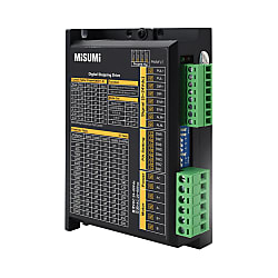
Click this image to zoom it.Nhấp vào hình ảnh này để phóng to.
Move the mouse over or click the image to zoom


- Volume Discount
Copy Part Number URL to Clipboard
The part number URL has been copied into your clipboard.
-
- From :
- 665,277VND/Unit

-
- Order Qty :
-
-
- Total Price :
- ---
-
- Days to ship :
- ---
Select part number to Order Now/ Add to Cart
 Similar Products
 Product Detail
Product Description
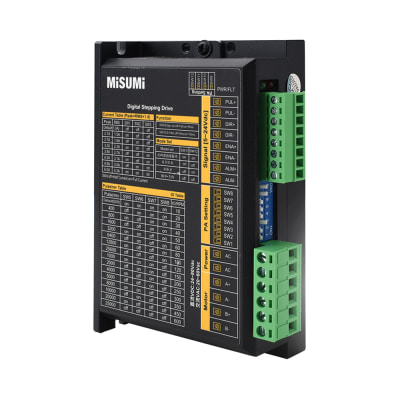
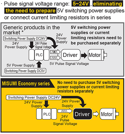
- Pulse signal voltage range: 5-24V, eliminating the need to prepare 5V switching power supplies or connect current limiting resistors in series.
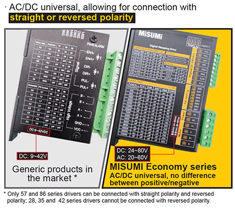
- AC/DC universal, allowing for connection with straight or reversed polarity.
- Can be order Motor individually or order as set product (Motor + Driver).
- The step angle is 1.8°.
- Driver Output Current(A): 1.0-4.3 A
- Driver Power Voltage(v): VDC24-80 or VAC20-60
- The stepping motor needs to be used with the stepping driver and cannot be directly connected to the power supply.
See more ...
Economy Stepper Motors 60 Series
- Achieve high torque with options for demanding applications.
- Operates on a versatile voltage range for flexible power integration.
- Enjoy precise movements with high subdivision capabilities.
- Built with high moment of inertia for reliable performance in tough conditions.
- Available as motor-only or complete sets with drivers for tailored setups.


MISUMI Standard

Cheaper Price

Product Variety

3D CAD Support
Product Overview of Stepping Motors
Product Features of Stepping Motors
Dimensional Drawing of Stepping Motors
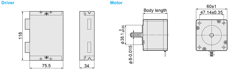
* The values of Stepping Motors in ( ) are reference values.
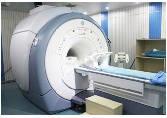
Example Use of Stepping Motors

Precautions of Stepping Motors
1. The maximum current set by the driver shall not exceed the maximum current of the motor.
2. The subdivision can only adjust the smoothness of rotation, rather than increase the precision.
3. The Stepping Motors needs to be used with the stepper driver, and cannot be directly connected to the power supply.
4. It is normal if the surface temperature of the Stepping Motors is between 80~90℃.
Part Number
- Incomplete part number.
Please use left hand selections to complete a part number.Incomplete part number.
Please use left hand selections to complete a part number.
| Part Number |
|---|
| C-60STM01+DR57A |
| Part Number | Price | Minimum Order Qty. | Volume Discount | Days to ShipSố ngày giao hàng | Type Details | Holding Torque (N·m) | Applicable Driver | Moment of Inertia (g.cm²) | Driver Output Current (A) | Driver Power Voltage (v) | Subdivision | Body Length (mm) |
|---|---|---|---|---|---|---|---|---|---|---|---|---|
1,401,698 VND | 1 Piece(s) | Available | Same day | Set (Motor + Driver) | 1.1 | C-DR57A | 275 | 1.0-4.3 | VDC24-80 or VAC20-60 | 200-25600 | 47 |
Loading...Tải…
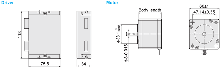
* The values in ( ) are reference values.
| Part Number | Step Angle (°) | Body Length (mm) | Number of Leads (pcs) | Current/Phase (A) | Holding Torque (N.m) | Moment of Inertia g.cm² | Applicable Driver | Driver Output Current (A) | Driver Power Voltage (V) | Subdivision |
| C-60STM01+DR57A | 1.8 | 47 | 4 | 2.8 | 1.1 | 275 | C-DR57A | 1.0-4.3 | VDC: 24-80 VAC: 20-60 | 200-25600 |
| C-60STM02+DR57A | 56 | 1.65 | 300 | |||||||
| C-60STM03+DR57A | 67 | 2.1 | 570 | |||||||
| C-60STM04+DR57A | 88 | 3.1 | 840 |
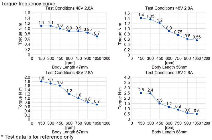
■ Torque-Frequency Curve
Basic InformationThông tin cơ bản
| Number of Leads(pcs) | 4 | Current/Phase(A) | 2.8 | Step Angle(°) | 1.8 |
|---|
Please check the type/dimensions/specifications of the part C-60STM01+DR57A in the Stepper Motors 60 Series series.Vui lòng kiểm tra kiểu/kích thước/thông số kỹ thuật của phần C-60STM01+DR57A trong chuỗi Stepper Motors 60 Series.
- The specifications and dimensions of some parts may not be fully covered. For exact details, refer toCác thông số kỹ thuật và kích thước của mã sản phẩm có thể không được bao phủ đầy đủ. Để biết chi tiết chính xác, hãy tham khảo manufacturer catalogsdanh mục nhà sản xuất ..
Frequently asked question (FAQ)FAQ
- Question:Question: What is the accuracy of the stepper motor? Is it cumulative?
- Answer:Answer: Generally, the accuracy of the stepper motor is 3 to 5% of the step angle. The single step deviation of the stepper motor will not affect the accuracy of the next step, so the accuracy of the stepper motor is not accumulated.
- Question:Question: What is the allowable exterior temperature of the stepper motor?
- Answer:Answer: Too high temperature of the stepper motor will first demagnetize the magnetic material of the motor, resulting in torque decrease or even loss. Therefore, the maximum allowable temperature of the motor exterior should depend on the demagnetization point of different motor magnetic materials. Generally speaking, the demagnetization point of magnetic materials is above 130℃, so it is completely normal for the exterior temperature of the stepper motor to be 80 to 90℃.
Products like this...
| Part Number |
|---|
| C-60STM01 |
| C-60STM02 |
| C-60STM02+DR57A |
| C-60STM03 |
| C-60STM03+DR57A |
| C-60STM04 |
| Part Number | Standard Unit Price | Minimum order quantity | Volume Discount | Days to ShipSố ngày giao hàng | Type Details | Holding Torque (N·m) | Applicable Driver | Moment of Inertia (g.cm²) | Driver Output Current (A) | Driver Power Voltage (v) | Subdivision | Body Length (mm) |
|---|---|---|---|---|---|---|---|---|---|---|---|---|
665,277 VND | 1 Piece(s) | Available | Same day | Motor Only | 1.1 | - | 275 | - | - | - | 47 | |
733,942 VND | 1 Piece(s) | Available | Same day | Motor Only | 1.65 | - | 300 | - | - | - | 56 | |
1,473,636 VND | 1 Piece(s) | Available | Same day | Set (Motor + Driver) | 1.65 | C-DR57A | 300 | 1.0-4.3 | VDC24-80 or VAC20-60 | 200-25600 | 56 | |
902,603 VND | 1 Piece(s) | Available | Same day | Motor Only | 2.1 | - | 570 | - | - | - | 67 | |
1,650,330 VND | 1 Piece(s) | Available | Same day | Set (Motor + Driver) | 2.1 | C-DR57A | 570 | 1.0-4.3 | VDC24-80 or VAC20-60 | 200-25600 | 67 | |
971,270 VND | 1 Piece(s) | Available | Same day | Motor Only | 3.1 | - | 840 | - | - | - | 88 |



How can we improve?
How can we improve?
While we are not able to respond directly to comments submitted in this form, the information will be reviewed for future improvement.
Customer Privacy Policy
Thank you for your cooperation.
While we are not able to respond directly to comments submitted in this form, the information will be reviewed for future improvement.
Please use the inquiry form.
Customer Privacy Policy