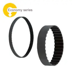
Timing Pulleys L

:
MISUMI
Product Overview
Usually, timing pulleys and timing belts are widely used to design mechanisms for transmitting rotational power generated by motors.
Driving and transmission are realized through the engagement between the teeth of timing pulleys and timing belts.
Driving and transmission are realized through the engagement between the teeth of timing pulleys and timing belts.
Dimensional Drawing

Specifications Overview
| Part Number |  Material Material |  Surface Treatment Surface Treatment | ||||
| Belt Width 12.7mm (1/2inch) | Belt Width 19.1mm (3/4inch) | Belt Width 25.4mm (1inch) | Belt Width 38.1mm (1.5inch) | Pulley | Flange | |
| A: 14 W: 19 L:31 (39) | A: 21 W: 26 L:38 (46) | A: 27 W: 32 L:44 (53) | A: 40 W: 45 L: 57 | |||
| E-ATPA□□L050 | E-ATPA□□L075 | E-ATPA□□L100 | E-ATPA□□L150 | Aluminum Alloy | Aluminum Alloy | Clear Anodized |
| E-ATPB□□L050 | E-ATPB□□L075 | E-ATPB□□L100 | E-ATPB□□L150 | Black Anodized | ||
| E-ATPK□□L050 | E-ATPK□□L075 | E-ATPK□□L100 | E-ATPK□□L150 | Hard Clear Anodize* | ||
| E-ATP□□L050 | E-ATP□□L075 | E-ATP□□L100 | E-ATP□□L150 | Equivalent to S45C | SPCC | Black Oxide Coating |
| E-ATPP□□L050 | E-ATPP□□L075 | E-ATPP□□L100 | E-ATPP□□L150 | Electroless Nickel Plating | ||
*Film hardness of hard clear anodize is 300HV~.
 Values in () for dimension L apply to the number of teeth 60 or 72.
The flange is riveted, and set screws are included for shaft bore specs. P, N or C.
If there are requirements for rust prevention, give priority to products made of aluminum alloy, stainless steel SUS304 and with surface treatment of electroless nickel plating.
For anti-rust performance and maintenance of metal materials and surface treatment, click here.
here.
 Values in () for dimension L apply to the number of teeth 60 or 72. The flange is riveted, and set screws are included for shaft bore specs. P, N or C. If there are requirements for rust prevention, give priority to products made of aluminum alloy, stainless steel SUS304 and with surface treatment of electroless nickel plating.
For anti-rust performance and maintenance of metal materials and surface treatment, click
 here.
here.Specification Table
| Part Number |  Pulley PulleyShape |  Shaft Bore Specs. Shaft Bore Specs. | Shaft Bore Specs. (1mm increments) | P.D. | O.D. | D | F | E | |||||||
 Type Type |  Number of Teeth Number of Teeth |  Type & Nominal Width Type & Nominal Width | H Round Hole | P Round Hole + Threaded Hole | N Keyway Hole + Tap | ||||||||||
| dH7 | |||||||||||||||
| Shape A | Shape B・D | Shape A | Shape B・D | Shape A | Shape B・D | ||||||||||
| (Aluminum Alloy) E-ATPA E-ATPB E-ATPK (S45C equivalent) E-ATP E-ATPP | 10 | L050 | A B | H P N | 6~20 | 6~18 | 6~14 | 6~14 | 8~14 | 8~14 | 30.32 | 29.56 | 22 | 36 | 24 |
| 12 | L050・L075 | 8~26 | 8~23 | 8~18 | 8~18 | 8~18 | 8~18 | 36.38 | 35.62 | 27 | 45 | 30 | |||
| 14 | L050 *A :14 *W :19 *L :31 (60・72=L:39) L075 *A :21 *W :26 *L :38 (60・72=L:46) L100 *A :27 *W :32 *L :44 (60・72=L:53) L150 *A :40 *W :45 *L :57 | 8~31 | 8~26 | 8~23 | 8~20 | 8~21 | 8~20 | 42.45 | 41.68 | 30 | 48 | 35 | |||
| 15 | 8~31 | 8~26 | 8~23 | 8~20 | 8~23 | 8~20 | 45.48 | 44.72 | |||||||
| 16 | 10~36 | 10~28 | 10~28 | 10~22 | 10~23 | 10~22 | 48.51 | 47.75 | 32 | 55 | 40 | ||||
| 17 | 10~36 | 10~30 | 10~28 | 10~24 | 10~26 | 10~23 | 51.54 | 50.78 | 34 | ||||||
| 18 | 10~41 | 10~32 | 10~33 | 10~26 | 10~34 | 10~23 | 54.57 | 53.81 | 36 | 61 | 45 | ||||
| 19 | 12~46 | 12~34 | 12~34 | 12~28 | 12~35 | 12~25 | 57.61 | 56.84 | 38 | 67 | 50 | ||||
| 20 | 12~46 | 12~36 | 12~34 | 12~30 | 12~35 | 12~26 | 60.64 | 59.88 | 40 | 67 | 50 | ||||
| 21 | 12~52 | 12~38 | 12~40 | 12~30 | 12~37 | 12~26 | 63.67 | 62.91 | 42 | 70 | 56 | ||||
| 22 | 12~53 | 12~41 | 12~44 | 12~33 | 12~38 | 12~30 | 66.70 | 65.94 | 45 | 80 | 60 | ||||
| 24 | 12~63 | 12~46 | 12~49 | 12~38 | 12~44 | 12~30 | 72.77 | 72.00 | 50 | 87 | 67 | ||||
| 25 | 12~63 | 12~46 | 12~49 | 12~38 | 12~45 | 12~30 | 75.80 | 75.04 | |||||||
| 26 | 12~63 | 12~46 | 12~49 | 12~38 | 12~45 | 12~30 | 78.83 | 78.07 | |||||||
| 28 | 12~71 | 12~46 | 12~57 | 12~38 | 12~50 | 12~30 | 84.89 | 84.13 | 95 | 75 | |||||
| 30 | 12~72 | 12~52 | 12~62 | 12~42 | 12~55 | 12~34 | 90.96 | 90.20 | 56 | 99 | 80 | ||||
| 32 | 14~76 | 14~52 | 14~65 | 14~42 | 14~55 | 14~34 | 97.02 | 96.26 | 104 | 84 | |||||
| 34 | 14~83 | 14~59 | 14~70 | 14~49 | 14~55 | 14~41 | 103.08 | 102.32 | 63 | 111 | 90 | ||||
| 36 | 14~85 | 14~59 | 14~70 | 14~49 | 14~55 | 14~41 | 109.15 | 108.39 | 123 | 102 | |||||
| 38 | 15~85 | 15~59 | 15~70 | 15~49 | 15~55 | 15~41 | 115.21 | 114.45 | 127 | 105 | |||||
| 40 | 15~85 | 15~59 | 15~70 | 15~49 | 15~55 | 15~41 | 121.28 | 120.51 | 63 | 131 | 110 | ||||
| 42 | 16~85 | 16~67 | 16~70 | 16~57 | 16~55 | 16~49 | 127.34 | 126.58 | 71 | 135 | 115 | ||||
| 44 | 16~85 | 16~67 | 16~70 | 16~57 | 16~55 | 16~49 | 133.40 | 132.64 | 140 | 120 | |||||
| 46 | 16~85 | 16~67 | 16~70 | 16~57 | 16~55 | 16~49 | 139.47 | 138.71 | 144 | 125 | |||||
| 48 | 16~85 | 16~67 | 16~70 | 16~57 | 16~55 | 16~49 | 145.53 | 144.77 | 152 | 130 | |||||
| 50 | 16~85 | 16~67 | 16~70 | 16~57 | 16~55 | 16~49 | 151.60 | 150.83 | 160 | 140 | |||||
Z-d≥2 for Shaft Bore Specs. V. Q(R)-d≥2 for Shaft Bore Specs. Y. For shape D, dimension E is the value in ( ). Shaft Bore Dia. 4.5 and 6.35, if falling within the selection range, can be selected for Shaft Bore Specs. H, P, V and F. Specify NK10 when New JIS Keyway Hole + Threaded Hole with shaft bore diameter of 10 and keyway width 4.0mm (height 1.8mm) is requested. For detailed dimensions of keyway, please click here. NK10, if falling within the selection range, can also be selected for Shaft Bore Specs. N. Shaft Bore Dia. 8, 9, 11, 13, 14, 17 and 21~50 are not available for Shaft Bore Specs. C. Shaft Bore Dia. 9 and 51~54 are not available for Shaft Bore Specs. N.
Product Features
Feature 1: L specification timing pulleys, suitable for general torque transmission design and high speed conveyance design.
Feature 2: L specification timing pulleys provide great transmission accuracy and efficiency, making them suitable for high-precision transmission and conveyance designs.
Feature 3: L specification timing pulleys have a wide range of load and speed ratios, applicable to most mechanisms and equipment.
Feature 4: MISUMI timing pulleys satisfy industrial standards, enabling for a reliable purchase and simple equipment maintenance.
Feature 5: MISUMI timing pulleys are available in various materials and suitable for a wide range of design environments.
Feature 6: MISUMI timing pulleys are made with meticulous attention to detail, allowing customers to make purchases with more confidence.

Usage Method
| Usage Method Example Drawing | Usage Method of Timing Wheel and Timing Belt |
 | ①Driving (The driven wheel is driven by the driving wheel for transmission) |
 | ②Linear driving (Reciprocating motion is carried out through the free-end toothed timing belt.) |
| Usage Method Example Drawing | Usage Method of Timing Wheel and Timing Belt |
 | ③Conveyance (Plates are conveyed by two toothed timing belts) |
 | ④Traction transmission (Workpieces are clamped and transmitted by the belt) |
Precautions
①For Shaft Bore Specs. P (round hole+threaded hole) or N, the attached set screws are shipped in the same package (may drop in the packaging bag).
②There is no threaded hole for Shaft Bore Specs. H (round hole).
③There may be no surface treatment in the shaft bore.
④t=2.0 for 60 and 72 toothed pulleys (Cut Flange).
⑤For the N keyway hole, the position relation between keyway and tooth is not fixed.
②There is no threaded hole for Shaft Bore Specs. H (round hole).
③There may be no surface treatment in the shaft bore.
④t=2.0 for 60 and 72 toothed pulleys (Cut Flange).
⑤For the N keyway hole, the position relation between keyway and tooth is not fixed.
Example of Use

Equipment Name: Ball Spline Lifting & Rotating Mechanism
Purpose:
Rotates the workpiece received from the previous process 90 degrees to lower it and transfers the workpiece to the next process.
Purpose of Timing Pulley:
The transmission of the timing pulley changes the direction of the collet. (Applicable to timing pulleys with specifications MXL, XL, L and H)
For details, please clickhere.
Purpose:
Rotates the workpiece received from the previous process 90 degrees to lower it and transfers the workpiece to the next process.
Purpose of Timing Pulley:
The transmission of the timing pulley changes the direction of the collet. (Applicable to timing pulleys with specifications MXL, XL, L and H)
For details, please click
here.Application Industries
| Semiconductor | Automotive | Smart Phones | ||
 |  |  | ||
| Medical | Electronic & Electrical | Robotics | ||
 |  |  |
Related Products
| Idler | Toothed Timing Belts L | Toothed Timing Belts | ||
 |  |  | ||
| Representative model: AATFW30-L100-20 | Representative model: TBN225L100 | Representative model: C-TBN322L100 |
Related Documents
Technical Data of Toothed Timing Belts and Timing Pulleys
①For the data on the selection of timing pulleys and toothed timing belts, tensioning force, etc. (drive), please clickhere and check.
②For the data on the selection of timing pulleys and toothed timing belts, tensioning force, etc. (transmission & conveyance), please clickhere and check.
③For the main causes and countermeasures for the damage, breakage, abnormal noise of timing toothed belts, please clickhere and check.
④For the reference data on the replacement time of toothed timing belts, please clickhere and check.
⑤For the data on dimensional tolerance of timing pulleys, please clickhere and check.
①For the data on the selection of timing pulleys and toothed timing belts, tensioning force, etc. (drive), please click
here and check.②For the data on the selection of timing pulleys and toothed timing belts, tensioning force, etc. (transmission & conveyance), please click
here and check.③For the main causes and countermeasures for the damage, breakage, abnormal noise of timing toothed belts, please click
here and check.④For the reference data on the replacement time of toothed timing belts, please click
here and check.⑤For the data on dimensional tolerance of timing pulleys, please click
here and check.