Timing Pulleys Keyless/High Torque/S5M

:
MISUMI
Product Overview
Usually, timing pulleys and timing belts are widely used to design mechanisms for transmitting rotational power generated by motors.
Driving and transmission are realized through the engagement between the teeth of timing pulleys and timing belts.
Driving and transmission are realized through the engagement between the teeth of timing pulleys and timing belts.
Dimensional Drawing

 The shaft bore may not have surface treatment.Bushings are available in Standard Type (ST Bushing) and Short Type (SH Bushing). Refer to Detailed Specifications of Bushings
Specifications Overview
| Part Number |  Material Material |  Surface Treatment Surface Treatment | ||||||
| Belt Width 10mm | Belt Width 15mm | Belt Width 25mm | Pulley | Flange | Bushing | Pulley | Flange | Bushing |
| A: 11 W: 16 | A: 17 W: 22 | A: 27 W: 32 | ||||||
| E-HTLA□□S5M100 | E-HTLA□□S5M150 | E-HTLA□□S5M250 | Aluminum Alloy 7A09 | Aluminum Alloy | Equivalent to S45C | Clear Anodized | - | |
| E-HTLK□□S5M100 | E-HTLK□□S5M150 | E-HTLK□□S5M250 | Hard Clear Anodize | - | ||||
| E-HTPL□□S5M100 | E-HTPL□□S5M150 | E-HTPL□□S5M250 | Equivalent to S45C | SPCC | Equivalent to S45C | Ferroferric Oxide Protective Film | ||
| E-HTLG□□S5M100 | E-HTLG□□S5M150 | E-HTLG□□S5M250 | Electroless Nickel Plating | |||||
Film hardness of hard clear anodize is 300HV~.If there are requirements for rust prevention, give priority to products with surface treatment of electroless nickel plating on other pages.Specification Table
| Part Number |  Pulley PulleyShape |  dH7 range (select Shaft Bore Dia. according to Table 1) dH7 range (select Shaft Bore Dia. according to Table 1) | P.D. | O.D. | F | E | |||||||
| S5M100 | S5M150 | S5M250 | |||||||||||
 Type Type |  Number of Teeth Number of Teeth |  Type & Nominal Width Type & Nominal Width | Shape E (ST Bushing) | Shape F (SH Bushing) | Shape E (ST Bushing) | Shape F (SH Bushing) | Shape E (ST Bushing) | Shape F (SH Bushing) | |||||
| E-HTLA E-HTLK E-HTPL E-HTLG | 22 | S5M100 *A:11 *W:16 S5M150 *A:17 *W:22 S5M250 *A:27 *W:32 | E F | 8 | - | - | - | - | - | 35.01 | 34.05 | 40 | 27 |
| 24 | 8・10 | 8 | 10 | 8 | 10 | 8 | 38.2 | 37.24 | 45 | 30 | |||
| 25 | 8・10 | 8 | 10 | 8 | 10 | 8 | 39.79 | 38.83 | |||||
| 26 | 8~12 | 8 | 10・11・12 | 8~12 | 10・11・12 | 8~12 | 41.38 | 40.42 | 48 | 35 | |||
| 28 | 8~12 | 8 | 10・11・12 | 8~12 | 10・11・12 | 8~12 | 44.56 | 43.6 | |||||
| 30 | 10~15 | - | 10~15 | 10・11・12 | 10~15 | 10・11・12 | 47.75 | 46.79 | 52 | 36 | |||
| 32 | 10~17 | 10~17 | 10・11・12 | 10~17 | 10・11・12 | 50.93 | 49.97 | 55 | 40 | ||||
| 34 | 10~17 | 10~17 | 10・11・12 | 10~17 | 10~17 | 54.11 | 53.15 | 61 | 45 | ||||
| 36 | 10~17 | 10~17 | 10・11・12 | 10~17 | 10~17 | 57.3 | 56.34 | ||||||
| 40 | 10~17 | 10~17 | 10・11・12 | 10~17 | 10~17 | 63.66 | 62.7 | 67 | 50 | ||||
| 44 | 12~25 | 12~25 | 12 | 12~25 | 12~25 | 70.03 | 69.07 | 74 | 58 | ||||
| 48 | 12~28 | 12~28 | 12 | 12~28 | 12~28 | 76.39 | 75.43 | 83 | 63 | ||||
| 50 | 12~32 | - | 12~32 | 12 | 12~32 | 12~32 | 79.58 | 78.62 | 87 | 67 | |||
| 60 | 12~32 | 12~40 | 12 | 12~40 | 12~35 | 95.49 | 94.53 | 99 | 80 | ||||
| 72 | 12~32 | 12~42 | 12 | 12~42 | 12~35 | 114.59 | 113.63 | 119 | 100 | ||||
Select Shaft Bore Dia. according to Table 1■Table 1: Shaft Bore Dia. Selection
| H7 | Allowable max. torque N・m | D | (L) | ||
| ST Bushing | SH Bushing | ST Bushing | SH Bushing | ||
| 8 | 16 | 8.5 | 25.5 | 24.5 | 8.5 |
| 10 | 39 | 18 | 30 | 29 | 10.5 |
| 11 | 43 | 20 | 31 | 30 | |
| 12 | 48 | 23 | 32 | 31 | |
| 14 | 73 | 37 | 35 | 36 | 12 |
| 15 | 78 | 39 | 36 | 37 | |
| 16 | 83 | 42 | 37 | 38 | 13 |
| 17 | 88 | 45 | 38 | 39 | |
| 18 | 154 | 48 | 43 | 40 | 14 |
| 19 | 163 | 49 | 45 | 42 | |
| 20 | 171 | 97 | 46 | 46 | |
| 22 | 186 | 110 | 48 | 47 | |
| 24 | 206 | 121 | 50 | 49 | |
| 25 | 216 | 124 | 52 | 51 | |
| 28 | 353 | 141 | 54 | 53 | 15.5 |
| 30 | 382 | 149 | 57 | 56 | |
| 32 | 412 | 163 | 59 | 58 | 16.5 |
| 35 | 451 | 173 | 63 | 61 | |
| 38 | 686 | - | 70 | - | 19 |
| 40 | 725 | 71 | |||
| 42 | 757 | 74 | 20 | ||
Using a bushing with electroless nickel plated surface reduces maximum allowable torque and axial load by 20%-30%.Product Features
Features of MISUMI Keyless Timing Pulleys
Feature 1: Keyless timing pulleys require no keyway machining, and round shaft and round hole can be used directly.
Urgent design changes can be made due to the reduction of cutting and machining time.
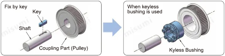
Feature 2: Keyless timing pulleys are connected with bolts only, allowing for easy installation and removal.
Equipment maintenance can be easily carried out without using a special tool. Parts are reusable, effectively reducing the cost.
Feature 3: Keyless timing pulleys enable free alignment at any position during assembly.
Alignment control is possible during assembly, thus eliminating the need to align the key and tooth in the design phase.

Feature 4: Keyless timing pulleys have no loosening. When a key is used, the keyway becomes loose, but there is no gap in the keyless bushing. It is therefore suitable for places where there are repeated forward and reverse rotations.
Long-term high coaxiality connection can be achieved. Suitable for servo motors and other places where there are repeated forward and reverse rotations.

Feature 1: Keyless timing pulleys require no keyway machining, and round shaft and round hole can be used directly.
Urgent design changes can be made due to the reduction of cutting and machining time.

Feature 2: Keyless timing pulleys are connected with bolts only, allowing for easy installation and removal.
Equipment maintenance can be easily carried out without using a special tool. Parts are reusable, effectively reducing the cost.

Feature 3: Keyless timing pulleys enable free alignment at any position during assembly.
Alignment control is possible during assembly, thus eliminating the need to align the key and tooth in the design phase.

Feature 4: Keyless timing pulleys have no loosening. When a key is used, the keyway becomes loose, but there is no gap in the keyless bushing. It is therefore suitable for places where there are repeated forward and reverse rotations.
Long-term high coaxiality connection can be achieved. Suitable for servo motors and other places where there are repeated forward and reverse rotations.

Usage Method
■Mounting method for keyless timing pulleys
①Wipe off the stains on the shaft surface and apply a layer of lubricant or grease. (Do not use any lubricant or grease that contains molybdenum abrasion inhibiting agent.)
②Also wipe the contact surface between the timing pulley and the bushing, and apply lubricant or grease. In addition, the fastening bolt thread surface and bearing surface must be applied lubricant or grease.
③Insert the timing pulley and bushing into the shaft after temporary assembly. (Do not tighten the bushing directly with the bolt without putting it through the shaft.)
④After positioning is completed, tighten the bolts gently (about 1/4 of the specified tightening torque) and diagonally in sequence with a torque wrench.
⑤Tighten with increased tightening torque (about 1/2 of the specified tightening torque).
⑥Tighten again to the specified tightening torque.
⑦Tighten the fastening bolt circumferentially in sequence.
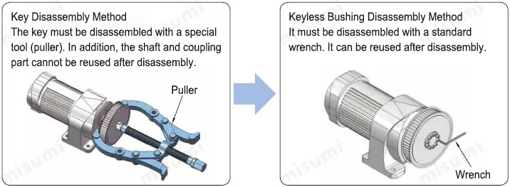
■Disassembly method for keyless timing pulleys
①Work with the unit at a complete stop.
②Loose the fastening bolt circumferentially in sequence
③Insert the bolt into the threaded hole for disassembly and evenly screw it in.
④When reinstalling, repeat the steps in “Installation”.
①Wipe off the stains on the shaft surface and apply a layer of lubricant or grease. (Do not use any lubricant or grease that contains molybdenum abrasion inhibiting agent.)
②Also wipe the contact surface between the timing pulley and the bushing, and apply lubricant or grease. In addition, the fastening bolt thread surface and bearing surface must be applied lubricant or grease.
③Insert the timing pulley and bushing into the shaft after temporary assembly. (Do not tighten the bushing directly with the bolt without putting it through the shaft.)
④After positioning is completed, tighten the bolts gently (about 1/4 of the specified tightening torque) and diagonally in sequence with a torque wrench.
⑤Tighten with increased tightening torque (about 1/2 of the specified tightening torque).
⑥Tighten again to the specified tightening torque.
⑦Tighten the fastening bolt circumferentially in sequence.
■Disassembly method for keyless timing pulleys
①Work with the unit at a complete stop.
②Loose the fastening bolt circumferentially in sequence
③Insert the bolt into the threaded hole for disassembly and evenly screw it in.
④When reinstalling, repeat the steps in “Installation”.
Precautions
① If there are requirements for rust prevention, give priority to products with surface treatment of electroless nickel plating on other pages.
Please refer to surface treatment and rust prevention methods
② When installing a keyless bushing, be sure to apply lubricant or grease to the shaft surface, the contact surface between the pulley and the bushing, and the fastening bolt.
Otherwise it will not be securely tightened and may cause the shaft to idle.
③Tighten the bolt after inserting the bushing into the shaft. (If the bolts is tightened before inserting the bushing, it will cause deformation of the bushing.)
④Use a torque spanner to tighten the bolts.
⑤Do not use bolts other than those supplied.
Please refer to
 surface treatment and rust prevention methods
② When installing a keyless bushing, be sure to apply lubricant or grease to the shaft surface, the contact surface between the pulley and the bushing, and the fastening bolt.
Otherwise it will not be securely tightened and may cause the shaft to idle.
③Tighten the bolt after inserting the bushing into the shaft. (If the bolts is tightened before inserting the bushing, it will cause deformation of the bushing.)
④Use a torque spanner to tighten the bolts.
⑤Do not use bolts other than those supplied.
Example of Use

■Mechanism name
Dustproof Lifting Machine
■Mechanism function
Lifting machine for heavy workpieces
Use in dusty places
■Function of Keyless Timing Pulleys
Rotates ball screws by means of a keyless toothed timing belt, lifting and lowering the positioning stage
For details, please click Dustproof Lifting Machine
Dustproof Lifting Machine
■Mechanism function
Lifting machine for heavy workpieces
Use in dusty places
■Function of Keyless Timing Pulleys
Rotates ball screws by means of a keyless toothed timing belt, lifting and lowering the positioning stage
For details, please click Dustproof Lifting Machine
Application Industries
| Smart Phones | Medical | Electronic & Electrical | ||
 |  |  | ||
| Automotive | Robotics | Lithium battery | ||
 |  |  |
Related Products
| S5M Timing Belt Idler Pulley | S5M Timing Belt | Timing Pulleys High Torque S5M | ||
 |  |  | ||
| C-AHTFW26-S5M150-10 | Representative model: C-HTBN230S5M-150 | E-HTPK26S5M150-B-NK10 | ||
| Advantage: Short delivery time, multiple types | Advantage: Short delivery time, multiple types | Advantage: Short delivery time, multiple types |
Related Documents
Technical Data of Toothed Timing Belts and Timing Pulleys
①Data on the selection of timing pulleys and timing toothed belts, tensioning force, etc. (drive).
②Data on the selection of timing pulleys and timing toothed belts, tensioning force, etc. (transmission & conveyance).
③Main causes and countermeasures for the damage, breakage, abnormal noise of toothed timing belts.
④Reference data on the replacement time of toothed timing belts.
⑤Data on dimensional tolerance of timing pulleys.