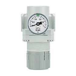
Regulator AR10-A to AR40-A
:
SMC
- Refer to the catalog for details on product specifications.
- Product images may be representative. Refer to the manufacturer's catalog for details.
SMC Regulator AR10-A to AR40-A.
[Features]
· Energy saving regulator.
· Pressure drop amount: Improved by up to 50%.
Regulator AR10-A to AR40-A: Detailed Examples

AR10-A: product images

AR20-A: product images

AR30-A: product images
Regulator AR10-A to AR40-A Specifications
Model number notation (standard specifications)

Model number example
| - | Code | Contents | (1) | |||||||
|---|---|---|---|---|---|---|---|---|---|---|
| Body size | ||||||||||
| 10 | 20 | 25 | 30 | 40 | ||||||
| (2) | Screw Type | No symbol | Metric thread (M5) | ● | - | - | - | - | ||
| Rc | - | ● | ● | ● | ● | |||||
| N | NPT | - | ● | ● | ● | ● | ||||
| F | G | - | ● | ● | ● | ● | ||||
| (3) | Piping connection port diameter | M5 | M5 | ● | - | - | - | - | ||
| 01 | 1/8 | - | ● | - | - | - | ||||
| 02 | 1/4 | - | ● | ● | ● | ● | ||||
| 03 | 3/8 | - | - | ● | ● | ● | ||||
| 04 | 1/2 | - | - | - | - | ● | ||||
| 06 | 3/4 | - | - | - | - | ● | ||||
| (4) | Option Note 1) | a | Mounting | No symbol | Without optional mounting parts | ● | ● | ● | ● | ● |
| B Note 2) | With Bracket | ● | ● | ● | ● | ● | ||||
| H | With set nut (for panel mounting) Note 3) | ● | ● | ● | ● | ● | ||||
| b | Pressure gauge Note 4) | No symbol | Without pressure gauge | ● | ● | ● | ● | ● | ||
| G | Round-type pressure gauge (without limit indicator) | ● | - | - | - | - | ||||
| Round-type pressure gauge (with limit indicator) | - | ● | ● | ● | ● | |||||
| M | Round-type pressure gauge (with color zone) | - | ● | ● | ● | ● | ||||
| (5) | Semi-standard | c | Set pressure Note 5) | No symbol | 0.05 to 0.7‑MPa setting | ● | ● | ● | ● | ● |
| 1 | 0.02 to 0.2‑MPa setting | ● | ● | ● | ● | ● | ||||
| d | Exhaust mechanism | No symbol | Relieving type | ● | ● | ● | ● | ● | ||
| N | Non-relieving type | ● | ● | ● | ● | ● | ||||
| e | Flow direction | No symbol | Flow direction: left → right | ● | ● | ● | ● | ● | ||
| R | Flow direction: right → left | ● | ● | ● | ● | ● | ||||
| f | Handle direction | No symbol | Handle downward | ● | ● | ● | ● | ● | ||
| Y | Handle upward | ● | ● | ● | ● | ● | ||||
| g | Pressure unit | No symbol | Nameplate and pressure gauge units: MPa | ● | ● | ● | ● | ● | ||
| Z Note 6) | Nameplate and pressure gauge units: psi | ○ Note 7) | ○ Note 7) | ○ Note 7) | ○ Note 7) | ○ Note 7) | ||||
- *Note 1) Options B, G, H, M are not assembled and are supplied loose at the time of shipment.
- *Note 2) Set nuts are included with the bracket.
- *Note 3) Products AR20-B to AR40-B are not interchangeably mountable with previous products AR20 to AR40.
- *Note 4) When the pressure gauge is attached, a 1.0 MPa will be fitted for standard (0.7‑MPa setting) type; 0.4 MPa for the 0.2‑MPa type (1.0‑MPa pressure gauge only for the AR10-A).
- *Note 5) Pressure can be set higher than the specification pressure in some cases, but use with the pressure within the specified range.
- *Note 6) Thread type: NPT. Under new Japanese measurement laws, this product is only available for sale outside of Japan (SI units are used in Japan). Round-type pressure gauge (with color zone): cannot be used in combination with M.
- *Note 7) ○ is for thread types M5 and NPT only.
Model number notation (Made-to-order specifications X406)

Made-to-order specifications X406: model number example
| - | Code | Contents | (1) | ||||||
|---|---|---|---|---|---|---|---|---|---|
| Body size | |||||||||
| 20 | 25 | 30 | 40 | ||||||
| (2) | Screw Type | No symbol | Rc | ● | ● | ● | ● | ||
| N | NPT | ● | ● | ● | ● | ||||
| F | G | ● | ● | ● | ● | ||||
| (3) | Piping connection port diameter | 01 | 1/8 | ● | - | - | - | ||
| 02 | 1/4 | ● | ● | ● | ● | ||||
| 03 | 3/8 | - | ● | ● | ● | ||||
| 04 | 1/2 | - | - | - | ● | ||||
| 06 | 3/4 | - | - | - | ● | ||||
| (4) | Note 1) Option | a | Mounting | No symbol | Without optional mounting parts | ● | ● | ● | ● |
| B Note 2) | With Bracket | ● | ● | ● | ● | ||||
| H | With set nut (for panel mounting) Note 3) | ● | ● | ● | ● | ||||
| b | Pressure gauge | No symbol | Without pressure gauge | ● | ● | ● | ● | ||
| G | Round-type pressure gauge (with limit indicator) | ● | ● | ● | ● | ||||
| M | Round-type pressure gauge (with color zone) | ● | ● | ● | ● | ||||
| (5) | Semi-standard | c | Exhaust mechanism | No symbol | Relieving type | ● | ● | ● | ● |
| N | Non-relieving type | ● | ● | ● | ● | ||||
| d | Flow direction | No symbol | Flow direction: left → right | ● | ● | ● | ● | ||
| R | Flow direction: right → left | ● | ● | ● | ● | ||||
| e | Handle direction | No symbol | Handle downward | ● | ● | ● | ● | ||
| Y | Handle upward | ● | ● | ● | ● | ||||
| f | Pressure unit | No symbol | Nameplate and pressure gauge units: MPa | ● | ● | ● | ● | ||
| Z Note 4) | Nameplate and pressure gauge units: psi | ○ Note 5) | ○ Note 5) | ○ Note 5) | ○ Note 5) | ||||
- *Note 1) Options B, G, H, M are not assembled and are supplied loose at the time of shipment.
- *Note 2) Set nuts are included with the bracket.
- *Note 3) Only for the AR20-A to AR40-A.
- *Note 4) Thread type: NPT is applicable. Under new Japanese measurement laws, this product is only available for sale outside of Japan (SI units are used in Japan). Round-type pressure gauge (with color zone): cannot be used in combination with M.
- *Note 5) ○ is for thread type NPT only.
Specifications
| Proof pressure | 1.5 MPa |
|---|---|
| Maximum operating pressure | 1.0 MPa |
| Set pressure range Note 1) | 0.05 to 0.4 MPa |
- *Note 1) Pressure can be set higher than the specification pressure in some cases, but use with the pressure within the specified range.
Applicable models
| Model | AR20-A | AR25-A | AR30-A | AR40-A | AR40-06-A |
|---|---|---|---|---|---|
| Piping connection port diameter | 1/8, 1/4 | 1/4, 3/8 | 1/4, 3/8 | 1/4, 3/8, 1/2 | 3/4 |
Model number notation (Made-to-order specifications X2068)

Made-to-order specifications X2068: model number example
| - | Code | Contents | (1) | ||||||
|---|---|---|---|---|---|---|---|---|---|
| Body size | |||||||||
| 20 | 25 | 30 | 40 | ||||||
| (2) | Screw Type | No symbol | Rc | ● | ● | ● | ● | ||
| N | NPT | ● | ● | ● | ● | ||||
| F | G | ● | ● | ● | ● | ||||
| (3) | Piping connection port diameter | 01 | 1/8 | ● | - | - | - | ||
| 02 | 1/4 | ● | ● | ● | ● | ||||
| 03 | 3/8 | - | ● | ● | ● | ||||
| 04 | 1/2 | - | - | - | ● | ||||
| 06 | 3/4 | - | - | - | ● | ||||
| (4) | Note 1) Option | a | Mounting | No symbol | Without optional mounting parts | ● | ● | ● | ● |
| B Note 2) | With Bracket | ● | ● | ● | ● | ||||
| H | With set nut (for panel mounting) Note 3) | ● | ● | ● | ● | ||||
| b | Pressure gauge | No symbol | Without pressure gauge | ● | ● | ● | ● | ||
| G | Round-type pressure gauge (with limit indicator) | ● | ● | ● | ● | ||||
| M | Round-type pressure gauge (with color zone) | ● | ● | ● | ● | ||||
| (5) | Semi-standard | c | Exhaust mechanism | No symbol | Relieving type | ● | ● | ● | ● |
| N | Non-relieving type | ● | ● | ● | ● | ||||
| d | Flow direction | No symbol | Flow direction: left → right | ● | ● | ● | ● | ||
| R | Flow direction: right → left | ● | ● | ● | ● | ||||
| e | Handle direction | No symbol | Handle downward | ● | ● | ● | ● | ||
| Y | Handle upward | ● | ● | ● | ● | ||||
| f | Pressure unit | No symbol | Nameplate and pressure gauge units: MPa | ● | ● | ● | ● | ||
| Z Note 4) | Nameplate and pressure gauge units: psi | ○ Note 5) | ○ Note 5) | ○ Note 5) | ○ Note 5) | ||||
- *Note 1) Options B, G, H, M are not assembled and are supplied loose at the time of shipment.
- *Note 2) Set nuts are included with the bracket.
- *Note 3) Only for the AR20-A to AR40-A.
- *Note 4) Thread type: NPT is applicable. Under new Japanese measurement laws, this product is only available for sale outside of Japan (SI units are used in Japan). Round-type pressure gauge (with color zone): cannot be used in combination with M.
- *Note 5) ○ is for thread type NPT only.
Specifications
| Proof pressure | 1.5 MPa |
|---|---|
| Maximum operating pressure | 1.0 MPa |
| Set pressure range | 0.05 to 0.85 MPa |
Applicable models
| Model | AR20-A | AR25-A | AR30-A | AR40-A | AR40-06-A |
|---|---|---|---|---|---|
| Piping connection port diameter | 1/8, 1/4 | 1/4, 3/8 | 1/4, 3/8 | 1/4, 3/8, 1/2 | 3/4 |
Standard specification
| Model | AR10-A | AR20-A | AR25-A | AR30-A | AR40-A | AR40-06-A |
|---|---|---|---|---|---|---|
| Piping connection port diameter | M5 × 0.8 | 1/8, 1/4 | 1/4, 3/8 | 1/4, 3/8 | 1/4, 3/8, 1/2 | 3/4 |
| Pressure gauge connection port size | 1/16 Note) | 1/8 | ||||
| Applicable fluids | Air | |||||
| Ambient temperature and working fluid temperature | -5 to +60°C (no freezing) | |||||
| Proof pressure | 1.5 MPa | |||||
| Maximum operating pressure | 1.0 MPa | |||||
| Set pressure range | 0.05 to 0.7 MPa | |||||
| Structure | Relieving type | |||||
| Weight (kg) | 0.06 | 0.17 | 0.19 | 0.34 | 0.58 | 0.60 |
- Note) Use a bushing (part no.: 131368) when connecting R1/8 type pressure gauges to Rc1/16 connection ports.
Options / Part No.
| Option specification | Model | |||||||
|---|---|---|---|---|---|---|---|---|
| AR10-A | AR20-A | AR25-A | AR30-A | AR40-A | AR40-06-A | |||
| Bracket assembly Note 1) | AR12P-270AS | AR22P-270AS | AR27P-270AS | AR32P-270AS | AR42P-270AS | AR42P-270AS | ||
| Set nut | AR12P-260S | AR22P-260S | AR22P-260S | AR32P-260S | AR42P-260S | AR42P-260S | ||
| Pressure gauge | Round-type Note 2) | Standard | G27-10-R1 | G36-10-□01 | G46-10-□01 | |||
| 0.02 to 0.2‑MPa setting | G27-10-R1Note 3) | G36-4-□01 | G46-4-□01 | |||||
| Round-type Note 2) (with color zone) | Standard | - | G36-10-□01-L | G46-10-□01-L | ||||
| 0.02 to 0.2‑MPa setting | - | G36-4-□01-L | G46-4-□01-L | |||||
- *Note 1) Assembly of a bracket and set nuts.
- *Note 2) The □ in the part numbers for round-type pressure gauges indicates the connection thread type. Insert no symbol for Rc, and use "N" for NPT. Contact the manufacturer separately regarding NPT connection thread types and for psi unit specification pressure gauges.
- *Note 3) Pressure gauge for standard type.
Structural Drawings

AR10-A structural drawing

AR20-A/40-06-A: structural drawings
Component Parts
| Number | Part name | Materials | Model | Additional notes |
|---|---|---|---|---|
| 1 | Body | Zinc die-cast | AR10-A | Urban white |
| Die-cast aluminum | AR20-A to AR40-A | |||
| 2 | Bonnet | Polyacetal | AR10-A to AR40-A | Urban white |
Replacement Parts
| Number | Part name | Materials | Part number | |||||
|---|---|---|---|---|---|---|---|---|
| AR10-A | AR20-A | AR25-A | AR30-A | AR40-A | AR40-06-A | |||
| 3 | Valve assembly | SUS, HNBR | AR10P-090S | AR22P-060AS | AR32P-060AS | AR42P-060AS | ||
| 4 | Diaphragm assembly | Weatherable NBR | AR10P-150AS Note) | AR22P-150AS | AR32P-150AS | AR42P-150AS | ||
| 5 | Valve guide assembly | Polyacetal | 131329 | AR22P-050AS | AR32P-050AS | AR42P-050AS | ||
- *Note) The AR10-A is a piston type. Assembly is of a piston and a seal (KSYP-13).
Regulator AR10-A to AR40-A Dimensions
(Unit: mm)

Regulator AR10-A to AR40-A: dimensional drawings
| Model | Standard specification | Option specification | |||||||||||||||||||||
|---|---|---|---|---|---|---|---|---|---|---|---|---|---|---|---|---|---|---|---|---|---|---|---|
| Round-type pressure gauge | Round-type pressure gauge (with color zone) | Bracket mounting dimensions | Panel mount | ||||||||||||||||||||
| P 1 | P 2 | A | B Note) | C | D | F | J | H | J | H | J | M | N | Q | R | S | T | U | V | W | Y | Z | |
| AR10-A | M5 × 0.8 | 1/16 | 25 | 47.4 | 11 | 12.5 | M18 × 1 | 12.5 | ø26 (diameter 26 mm) | 26 | - | - | 25 | 28 | 30 | 4.5 | 6.5 | 40 | 2 | 18 | 18.5 | - | - |
| AR20-A | 1/8, 1/4 | 1/8 | 40 | 67.4 | 23.5 | 22 | M36 × 1.5 | 22 | ø37.5 (diameter 37.5 mm) | 58.5 | ø37.5 (diameter 37.5 mm) | 59.5 | 30 | 34 | 43.9 | 5.4 | 15.4 | 55 | 2.3 | 27.3 | 36.5 | 17.5 | 6 |
| AR25-A | 1/4, 3/8 | 1/8 | 53 | 70.4 | 23.5 | 22 | M36 × 1.5 | 22 | ø37.5 (diameter 37.5 mm) | 58.5 | ø37.5 (diameter 37.5 mm) | 59.5 | 30 | 34 | 44.3 | 5.4 | 15.4 | 55 | 2.3 | 30.3 | 36.5 | 17.5 | 6 |
| AR30-A | 1/4, 3/8 | 1/8 | 53 | 83.5 | 27 | 28.5 | M45 × 1.5 | 28.5 | ø37.5 (diameter 37.5 mm) | 65 | ø37.5 (diameter 37.5 mm) | 66 | 41 | 36 | 46 | 6.5 | 24 | 65 | 2.3 | 32.5 | 45.5 | 22.5 | 7 |
| AR40-A | 1/4, 3/8, 1/2 | 1/8 | 70 | 100 | 33.5 | 34.5 | M52 × 1.5 | 34.5 | ø42.5 (diameter 42.5 mm) | 72 | ø42.5 (diameter 42.5 mm) | 72 | 50 | 38 | 54 | 8.5 | 26.5 | 70 | 2.3 | 38.4 | 52.5 | 26 | 7 |
| AR40-06-A | 3/4 | 1/8 | 75 | 101.5 | 33.5 | 34.5 | M52 × 1.5 | 34.5 | ø42.5 (diameter 42.5 mm) | 72 | ø42.5 (diameter 42.5 mm) | 72 | 50 | 38 | 55.5 | 8.5 | 26.5 | 70 | 2.3 | 39.9 | 52.5 | 26 | 7 |
- *Note) The dimension B is the length when the filter regulator knob (handle) is unlocked.