Sealed compact basic switch D2VW
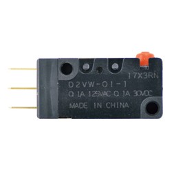
Seal type (IP67 compliant: except terminal part) basic compact size.
[Features]
· Stable sealing is ensured by using epoxy resin. Usable at watery and dusty places.
· The internal structure uses proven V type series mechanism to achieve greater system and high durability. Fitting similar to V type.
· Compliant with the applications requiring environmental resistance such as automobiles, agricultural machinery, large appliances, and business equipment.
Drawing
Pin push button type

Specifications Table
| 300 mm type | 1,000 mm type | |
|---|---|---|
| L | 300±10 | 1,000±30 |
Performance
| Items | Part number | ||
|---|---|---|---|
| D2VW-5 series | D2VW-01 series | ||
| Allowable operation speed | 0.1 mm to 1 m/s (for pin push button type) | ||
| Allowable operation frequency | Mechanical | 300 times/min | |
| Electrical | 60 times/min | ||
| Insulation resistance | 100 MΩ or more (at 500 V DC with insulation resistance tester) | ||
| Contact resistance (initial value) | Terminal type | 50 mΩ or less | |
| Lead wire type (300 mm) | 100 mΩ or less | ||
| Lead wire type (1,000 mm) | 200 mΩ or less | ||
| Withstand voltage*1 | Between terminals of the same polarity | 1,000 V AC 50/60 Hz for 1 min | |
| Between current-carrying metal parts and ground | 1,500 V AC 50/60 Hz for 1 min | ||
| Between each terminal and non-current-carrying metal part | 1,500 V AC 50/60 Hz for 1 min | ||
| Vibration*2 | Malfunction | Frequency 10 to 55 Hz double amplitude 1.5 mm | |
| Impact*2 | Endurance | Max. 1,000 m/s2 | |
| Malfunction | Max. 300 m/s2 | ||
| Durability | Mechanical | More than 10 million times (60 times/min) | |
| Electrical | More than 100,000 times (30 times/min) | More than 1 million times (30 times/min) | |
| Protective Structure | Terminal type | IEC IP67 (excluding the terminals on terminal models) | |
| Lead wire type | IEC standard IP67 | ||
| Appliance Class | Class I | ||
| PTI (Proof Tracking Index) | 175 | ||
| Operating temperature range | -40 to +85℃ 60% RH or less (no freezing or condensation) | ||
| Operating humidity range | 95% RH or less (+5 to +35℃) | ||
| Weight | Approximately 7 g (for terminal type pin push button type) | ||
*The values given above are initial values.
* 1. The withstand voltages are those when a separator is used.
*2. The given values apply to the free position and total travel position for the pin push button type; the total travel position for the lever type. The closed or open circuit of the contact is within 1 ms.
Product Specification
Operating characteristics
| Type | Actuator | Part number | Operating force | Release force | Pre travel | Over travel | Movement differential | Operating position |
|---|---|---|---|---|---|---|---|---|
| max.OF | min. RF | max. PT | min. OT | max. MD | OP | |||
| Terminal | Pin push button type | D2VW-5-1 D2VW-01-1 | 1.96 N | 0.29 N | 1.2 mm | 1.0 mm | 0.4 mm | 14.7 +/- 0.4 mm |
| Lead | Pin push button type | D2VW-5-1M D2VW-5-1M-0 D2VW-01-1M D2VW-01-1M-0 | 1.96 N | 0.29 N | 1.2 mm | 1.0 mm | 0.4 mm | 14.7 +/- 0.4 mm |
| Hinge Short lever type | D2VW-5L1A-1M D2VW-5L1A-1M-0 D2VW-01L1A-1M D2VW-01L1A-1M-0 | 1.96 N | 0.20 N | 1.6 mm | 0.8 mm | 0.5 mm | 15.2 +/- 0.5 mm | |
| Hinge lever type | D2VW-5L1-1M D2VW-5L1-1M-0 D2VW-01L1-1M D2VW-01L1-1M-0 | 1.18 N | 0.15 N | 4.0 mm | 1.6 mm | 0.8 mm | 15.2 +/- 1.2 mm | |
| Hinge Long lever type | D2VW-5L1B-1M D2VW-5L1B-1M-0 D2VW-01L1B-1M D2VW-01L1B-1M-0 | 0.59 N | 0.05 N | 9.0 mm | 3.2 mm | 2.0 mm | 15.2+/-2.6 mm | |
| Hinge simulated roller lever type | D2VW-5L3-1M D2VW-5L3-1M-0 D2VW-01L3-1M D2VW-01L3-1M-0 | 1.18 N | 0.15 N | 4.0 mm | 1.6 mm | 0.8 mm | 18.7+/-1.2 mm | |
| Hinge roller Short lever type | D2VW-5L2A-1M D2VW-5L2A-1M-0 D2VW-01L2A-1M D2VW-01L2A-1M-0 | 2.25 N | 0.20 N | 1.6 mm | 0.8 mm | 0.5 mm | 20.7+/-0.6 mm | |
| Hinge roller lever type | D2VW-5L2-1M D2VW-5L2-1M-0 D2VW-01L2-1M D2VW-01L2-1M-0 | 1.18 N | 0.15 N | 4.0 mm | 1.6 mm | 0.8 mm | 20.7+/-1.2 mm |
*The values for operating characteristics apply to operation in the A direction (down).
Model number display
Model Standard

Contact Specifications


The color in the parentheses indicates the color of the lead wire
Technical Information
Rating
| Type | Rated Voltage | Items |
|---|---|---|
| Resistant load | ||
| D2VW-5 series | AC250V AC125V | 5A 5A |
| 30 V DC | 5A | |
| D2VW-01 series | AC125V | 0.1 A |
| 30 V DC | 0.1 A |
*The above ratings are based on tests conducted under the following conditions.
(1) Ambient temperature: 20+/-2°C
(2) Ambient humidity: 65 +/- 5% RH
(3) Operation frequency: 30 times/min
Contact Specifications
| Items | Type | ||
|---|---|---|---|
| D2VW-5 series | D2VW-01 series | ||
| Contact | Specifications | Rivet | Crossbar |
| Material | Silver Alloy | Gold Alloy | |
| Interval (standard value) | 0.5 mm | ||
| Inrush Current | Normally closed | Max. 15 A | - |
| Normally open | Max. 15 A | - | |
| Minimum applicable load (reference value) * | 5 V DC 160 mA | 5 V DC 1 mA | |
* For the minimum applicable load, refer to "· Using microloads" under "Correct Usage".
Usage Examples
Mounting Hole Dimensions

Precautions for use
Installation
The switch should be securely installed using M3 screws and plain washers or spring lock washers, etc. The tightening torque should be 0.39 to 0.59 N⋅m.
Operating body
With the pin push button models, set the switch so that the push button can be pushed in from directly above. The push button is covered with a rubber cap, and if a load is applied to the push button from the lateral direction, the button may be damaged or the sealing capability may deteriorate.

Handling
Handle the switch with care to prevent the seal rubber on the push button from breaking.
Using Microloads
Using the switch with general loads during opening and closing the microload circuit may cause contact failure. Referring to the figure below, you should use the switch within the range of the usage area. Even when the microload type is used within the area shown in the figure below, if a load that generates an inrush current, etc., is applied at the time of opening and closing, the contact will be subjected to severe contact wear and tear, which may cause a decrease in durability. Therefore, a contact protection circuit should be inserted if necessary. The minimum applicable load is the N level reference value. It represents the failure level at a reliability level of 60% (λ60).
(JIS C5003)
λ60 = 0.5 x 10⁻⁶ /times indicates that failures of 1/2,000,000 times or less are estimated at a reliability level of 60%.

Cautions and Prohibitions
Safety Precautions
Protective structure
Do not use it underwater.
The lead wire type satisfies the test conditions for the following regulations, but all of these tests are to check the ingress of water after being left in water for a certain period of time, not for switching operation underwater.
JIS C0920: Degrees of protection provided by enclosures (IP code)
IEC 60529: Degrees of protection provided by enclosures (IP Code)
Protection rating: IP67 (Check for water ingress after it was left in water 1 m deep for 30 minutes)
Protection against adhesion of chemicals, etc.
Avoid contact with oil and chemicals.
Otherwise, it may alter or deteriorate the materials used.
About Soldering
- Connection to soldering terminals
When soldering the lead wire to the terminal, first insert the lead wire conductor through the terminal hole and conduct soldering.
As a general rule, the processing time for soldering should be 5 seconds or less with a soldering iron tip temperature of 350 to 400°C, and no external force should be applied for 1 minute after soldering. Working at excessive temperatures or heating for long periods of time can cause deterioration of switch characteristics.