Single Axis Robots E-MCHE5 / E-MCH5 Screw Drive, Fully-Sealed Type(For Clean Environment)

:
MISUMI
- Ground Ball Screw Type E-MTHE&E-MCHE Launched in Nov 2025 Click here>>New Catalog
- The product does not come with a driver, which must be purchased separately
- The product comes with a sensor kit, which is unnecessary to select
Economy series Aluminum Alloy Screw Drive Actuators E-MCHE5 Series product only includes the main unit, not the driver, which must be purchased separately. The product comes with a sensor kit, for which only mounting direction needs to be selected.
Product Overview
-Single Axis Robots, Economy series Aluminum Alloy Actuators are transmission devices integrating ball screws and guides, which are indispensable for the production process.
-Up to ±0.01 or less.
-The new type has been available since Nov 2025 and is our recommended model with lower noise and improved quality.
Please see the comparison with the previous model >>here.
Dimensional Drawing
■Material Specifications
| Components | Body | Guide | Ball Screw | Nut | Slide Block | Cover |
 Material Material | Aluminum Alloy | Carbon Steel | Bearing Steel | SCM415 | Aluminum Alloy | Aluminum Alloy |
 Surface Treatment Surface Treatment | Clear Anodized | - | - | - | Clear Anodized | Clear Anodized |
■ Single Axis Robots Motor Connection Diagram

BC Motor Direct

Dimension (mm), Mass (kg)
BM Motor Bottom Down

BR Motor Right Folded
Dimension (mm), Mass (kg)
BL Motor Left Folded
Dimension (mm), Mass (kg)

■ Basic Specifications
■ Model Specifications
 A motor is not included to this product and it must be purchased separately.
When the stroke exceeds 600mm, ball screw resonance will occur. In this case, reduce the movement speed.
Select a motor with brake for vertical use.
When the motor brand is specified as Z, the motor shaft diameter and installation dimensions must be provided.
As the drawings are schematic diagrams, please confirm the detailed dimensions according to CAD data.
■ Accessories
 Unit (mm)
■ List of Recommended Servo Motors
■ Motor mounting hole diagram

Product Features

BC Motor Direct

Dimension (mm), Mass (kg)
| Effective Stroke | 50 | 100 | 150 | 200 | 250 | 300 | 350 | 400 | 450 | 500 | 550 | 600 | 650 | 700 | 750 | 800 |
| L | 216 | 266 | 316 | 366 | 416 | 466 | 516 | 566 | 616 | 666 | 716 | 766 | 816 | 866 | 916 | 966 |
| A | 60 | 30 | 40 | 50 | 60 | 30 | 40 | 50 | 60 | 30 | 40 | 50 | 60 | 30 | 40 | 50 |
| M | 2 | 4 | 5 | 6 | 7 | 9 | 10 | 11 | 12 | 14 | 15 | 16 | 17 | 19 | 20 | 21 |
| N | 3 | 5 | 6 | 7 | 8 | 10 | 11 | 12 | 13 | 15 | 16 | 17 | 18 | 20 | 21 | 22 |
| KG | 2.1 | 2.2 | 2.3 | 2.4 | 2.5 | 2.6 | 2.7 | 2.8 | 2.9 | 3.0 | 3.1 | 3.2 | 3.3 | 3.4 | 3.5 | 3.6 |
BM Motor Bottom Down

Dimension (mm), Mass (kg)
| Effective Stroke | 50 | 100 | 150 | 200 | 250 | 300 | 350 | 400 | 450 | 500 | 550 | 600 | 650 | 700 | 750 | 800 |
| L | 210 | 260 | 310 | 360 | 410 | 460 | 510 | 560 | 610 | 660 | 710 | 760 | 810 | 860 | 910 | 960 |
| A | 60 | 30 | 40 | 50 | 60 | 30 | 40 | 50 | 60 | 30 | 40 | 50 | 60 | 30 | 40 | 50 |
| M | 2 | 4 | 5 | 6 | 7 | 9 | 10 | 11 | 12 | 14 | 15 | 16 | 17 | 19 | 20 | 21 |
| N | 3 | 5 | 6 | 7 | 8 | 10 | 11 | 12 | 13 | 15 | 16 | 17 | 18 | 20 | 21 | 22 |
| KG | 2.1 | 2.2 | 2.3 | 2.4 | 2.5 | 2.6 | 2.7 | 2.8 | 2.9 | 3.0 | 3.1 | 3.2 | 3.3 | 3.4 | 3.5 | 3.6 |
BR Motor Right Folded

Dimension (mm), Mass (kg)
| Effective Stroke | 50 | 100 | 150 | 200 | 250 | 300 | 350 | 400 | 450 | 500 | 550 | 600 | 650 | 700 | 750 | 800 |
| L | 210 | 260 | 310 | 360 | 410 | 460 | 510 | 560 | 610 | 660 | 710 | 760 | 810 | 860 | 910 | 960 |
| A | 60 | 30 | 40 | 50 | 60 | 30 | 40 | 50 | 60 | 30 | 40 | 50 | 60 | 30 | 40 | 50 |
| M | 2 | 4 | 5 | 6 | 7 | 9 | 10 | 11 | 12 | 14 | 15 | 16 | 17 | 19 | 20 | 21 |
| N | 3 | 5 | 6 | 7 | 8 | 10 | 11 | 12 | 13 | 15 | 16 | 17 | 18 | 20 | 21 | 22 |
| KG | 2.1 | 2.2 | 2.3 | 2.4 | 2.5 | 2.6 | 2.7 | 2.8 | 2.9 | 3.0 | 3.1 | 3.2 | 3.3 | 3.4 | 3.5 | 3.6 |
BL Motor Left Folded

Dimension (mm), Mass (kg)
| Effective Stroke | 50 | 100 | 150 | 200 | 250 | 300 | 350 | 400 | 450 | 500 | 550 | 600 | 650 | 700 | 750 | 800 |
| L | 210 | 260 | 310 | 360 | 410 | 460 | 510 | 560 | 610 | 660 | 710 | 760 | 810 | 860 | 910 | 960 |
| A | 60 | 30 | 40 | 50 | 60 | 30 | 40 | 50 | 60 | 30 | 40 | 50 | 60 | 30 | 40 | 50 |
| M | 2 | 4 | 5 | 6 | 7 | 9 | 10 | 11 | 12 | 14 | 15 | 16 | 17 | 19 | 20 | 21 |
| N | 3 | 5 | 6 | 7 | 8 | 10 | 11 | 12 | 13 | 15 | 16 | 17 | 18 | 20 | 21 | 22 |
| KG | 2.1 | 2.2 | 2.3 | 2.4 | 2.5 | 2.6 | 2.7 | 2.8 | 2.9 | 3.0 | 3.1 | 3.2 | 3.3 | 3.4 | 3.5 | 3.6 |
Specification Table

■ Basic Specifications
| Drive Method | Ball Screw | |
| Ball Screw | Accuracy grade | C7 |
| O.D. (mm) | ø12 | |
| Body width (mm) | 51 | |
| High Rigidity Linear Guide (mm) | W24xH8.5 | |
| Drive Power (W) | 100 | |
| Operating Environment | Low-Dust Environment | |
■ Model Specifications
| Part Number |  Lead (mm) Lead (mm) |  Stroke Stroke(50m increments) |  Motor Position |  Motor Brand |  Motor Power |  Sensor Position | Repetitive Positioning Accuracy (mm) | Max. Payload (kg) | Max. Speed (mm/sec) | Rated Thrust (N) | |
 Type Type | Horizontal Use | Vertical Use | |||||||||
| E-MCH5 (Rolled Screw Shaft) E-MCHE5 (Ground Screw Shaft) | 5 | 50~800 | BC (Motor Direct Connection) BM (Motor Bottom Down) BL (Motor Left Folded) BR (Motor Right Folded) | M (Misumi / Mitsubishi) P (Panasonic) Y (Yaskawa) T (Delta Electronics) Z (Prepared by Customer) | 10 (100W) | C (External Motor Side) *Left Side D (External Motor Opposite Side) *Right Side *For Motor Position BC and BM | ±0.01 | 10 | 3 | 250 | 341 |
| 10 | 5 | 1.5 | 500 | 170 | |||||||
 A motor is not included to this product and it must be purchased separately.When the stroke exceeds 600mm, ball screw resonance will occur. In this case, reduce the movement speed.Select a motor with brake for vertical use.When the motor brand is specified as Z, the motor shaft diameter and installation dimensions must be provided.As the drawings are schematic diagrams, please confirm the detailed dimensions according to CAD data.
■ Max. Movement Speed (mm/sec)
Values in the table are reference values calculated according to the critical speed and DN value of the ball screw.
Values in the table are maximum safety speeds available for each stroke. As ball screws may resonate at longer strokes, such conditions as abnormal sound and vibrationmay occur when operating at the maximum speed. Therefore, the moving speed should be reduced appropriately.
| Part Number | Lead (mm) | Motor Power (W) | Max. Movement Speed (mm/sec) | |||||||||||||||
| 50 | 100 | 150 | 200 | 250 | 300 | 350 | 400 | 450 | 500 | 550 | 600 | 650 | 700 | 750 | 800 | |||
| E-MCH5 (Rolled Screw Shaft) E-MCHE5 (Ground Screw Shaft) | 5 | 100 | 250 | 225 | 200 | 175 | 150 | |||||||||||
| 10 | 500 | 450 | 400 | 350 | 300 | |||||||||||||
Values in the table are reference values calculated according to the critical speed and DN value of the ball screw.Values in the table are maximum safety speeds available for each stroke. As ball screws may resonate at longer strokes, such conditions as abnormal sound and vibrationmay occur when operating at the maximum speed. Therefore, the moving speed should be reduced appropriately.■ Accessories
| Accessories | Accessory Name | Part Number | Quantity | ||
| Sensor | C-MSX672N-2M (NPN) | 3 | |||
| Motor connection method | BC | Coupling (mm) | 8×8 Motor Side (100W) | 1 | |
| BL/BR/BM | Ball Screw End Timing Pulley | 3GT-22 Teeth | 1 | ||
| Motor End Timing Pulley | 3GT-22 Teeth | 1 | |||
| Timing Belt | 3GT-180-9 | 1 | |||
Parameters Use
■ Sensing Line Wiring Diagram


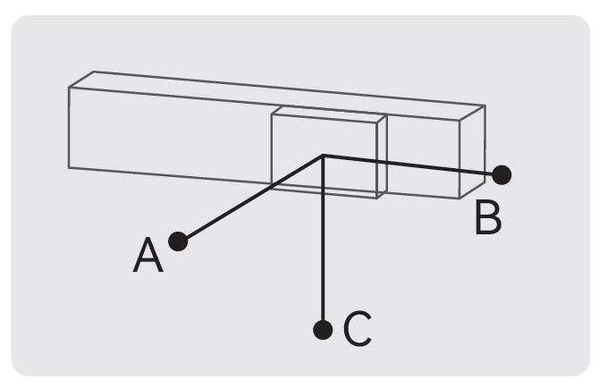
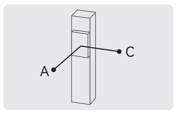
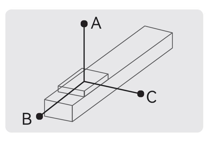
■ Allowable load center of gravity overhang (mm)
 Unit (mm)
 Unit (mm)
| Horizontal Installation | A | B | C | |
| Lead 5 | 5kg | 280 | 24 | 55 |
| 10kg | 120 | 10 | 22 | |
| Lead 10 | 3kg | 245 | 40 | 78 |
| 5kg | 140 | 22 | 43 | |
 Unit (mm)
| Wall Installation | A | B | C | |
| Lead 5 | 5kg | 51 | 30 | 195 |
| 10kg | 20 | 15 | 231 | |
| Lead 10 | 3kg | 74 | 37 | 131 |
| 5kg | 40 | 20 | 131 | |

Unit (mm)
| Vertical Installation | A | C | |
| Lead 5 | 1kg | 140 | 140 |
| 3kg | 47 | 47 | |
| Lead 10 | 1kg | 125 | 125 |
| 1.5kg | 83 | 83 | |
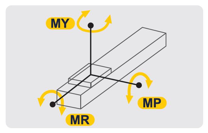
■ Static allowable moment N · m
Unit (N.m)

Unit (N.m)
| Horizontal Installation | |
| MY | 16 |
| MP | 20 |
| MR | 19 |
■ List of Recommended Servo Motors
| Brand | Motor Code | With/Without Brake | Motor Power | Power Voltage | Servo Motor Model | Servo Drive Model |
| MISUMI | M | Without Brake (Horizontal Use) | 100W | 220V | E-MASH1-0401 / E-MASH2-0401 / E-MASS2-0401 | (Standard Function) E-DFAS01P / E-DFAS01E (Full Function) E-DHAS01P / E-DHAS01E |
| With Brake (Vertical Use) | E-MASH1-0401B / E-MASH2-0401B / E-MASS2-0401B | |||||
| Mitsubishi | M | Without Brake (Horizontal Use) | 100W | 220V | HG-KR12 | MR-J4-10A |
| With Brake (Vertical Use) | HG-KR13B | |||||
| Panasonic | P | Without Brake (Horizontal Use) | 100W | 220V | MSMF012L1U2M | MADLN05SG |
| With Brake (Vertical Use) | MSMF012L1V2M | |||||
| Yaskawa | Y | Without Brake (Horizontal Use) | 100W | 220V | SGM7J01AFC6S | SGD7SR90A00A002 |
| With Brake (Vertical Use) | SGM7J01AFC6E | |||||
| Delta Electronics | T | Without Brake (Horizontal Use) | 100W | 220V | ECMA-C20401RS | ASD-B2-0121-B |
| With Brake (Vertical Use) | ECMA-C20401SS |
■ Motor mounting hole diagram

Product Features
1. Simple design and installation
2. Small size and light weight
3. High precision ±0.01
4. High rigidity
5. Low noise
6. Complete set of fittings
2. Small size and light weight
3. High precision ±0.01
4. High rigidity
5. Low noise
6. Complete set of fittings
Precautions
■ Avoid using Single Axis Robots drive products in the following environments
1. Dusty environment (especially metal powder)
2. Environment with splashing water and oil
3. Near fire sources
4. Environment with excessive organic solutions and salt
5. Environment with direct sunlight and heat radiation
6. Environment subject to strong vibration and shock
7. Environment with corrosive gas, combustible gas
■ Single Axis Robots operating environment
Operating environment: normal temperature (no freezing, non-condensation)
■ Comparison Table
<Test Conditions>
1. Dusty environment (especially metal powder)
2. Environment with splashing water and oil
3. Near fire sources
4. Environment with excessive organic solutions and salt
5. Environment with direct sunlight and heat radiation
6. Environment subject to strong vibration and shock
7. Environment with corrosive gas, combustible gas
■ Single Axis Robots operating environment
Operating environment: normal temperature (no freezing, non-condensation)
■ Comparison Table
| Old Specification | New Specification | ||
| Type | E-MTH / E-MCH | E-MTHE / E-MCHE | |
| Thread type | Rolled thread | Ground thread | |
| Appearance |  |  | |
| Noise test | Test model | E-MTH14-L10-200-BC-M40-C | E-MTHE14-L10-200-BC-M40-C |
| Max. noise level | 64.2 dB | 62.8 dB (–1.4 dB, approx. 2% reduction) | |
| Avg. noise level | 56.8 dB | 54.3 dB (–2.6 dB, approx. 5% reduction) | |
<Test Conditions>
| Test location | Quiet room | |
| Test environment | Ambient temperature 20–25 °C, relative humidity 70–75% | |
| Power source | 400 W servo motor (E-DHAS04P-F, E-MASH2-0604, MISUMI) | |
| Sound level meter | SM550 (3D type) | |
| Test platform | Granite platform | |
| Test software | MISUMI Edriver v1.2.0 | |
| Motion parameters | Stroke 200 mm; dwell time at target position 500 ms; | |
| speed 0.5 m/s; acceleration/deceleration 11 m/s² | ||
Example Use
