Single Axis Robots E-MGT8, Guide Built in Type, Semi-Sealed Type(General Use)

:
MISUMI
- **RoHS Compliant is available for some part numbers.
Please contact with MISUMI for detail effective date.
The product does not come with a driver, which must be purchased separately - The product does not come with a coupling, which must be purchased separately
- The product comes with a sensor kit, which is unnecessary to select
- The output shaft of Economy series Aluminum Alloy Embedded Actuators E-MGT8 Series is 10mm in diameter.
- The product only includes the main unit, not the driver and coupling, which must be purchased separately.
- The product comes with a sensor kit, for which only mounting direction needs to be selected.
Product Overview
The economical is an integrated transmission device that combines ball screw and embedded guide rail, and is an essential equipment for production and processing.
The aluminum alloy base is directly embedded in the steel track and then ground, the walking height and straightness accuracy are improved, up to ±0.02 or less.
Small size, easy to assemble
■ Low runing noise guaranteed
Every actuator's noise level is tested before shipment to ensure runing noise level below 70 dB
Test conditions:
- Noise level is measured in an inspection room without external environmental noise and includes motor noise.
- The noise meter is placed at a distance of 300 mm.
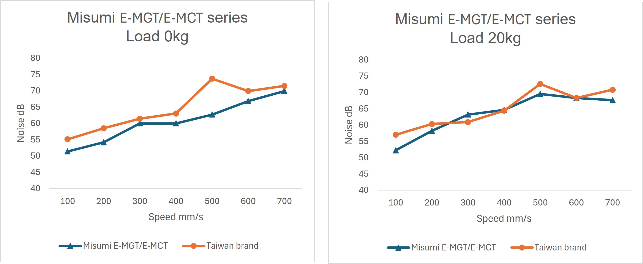
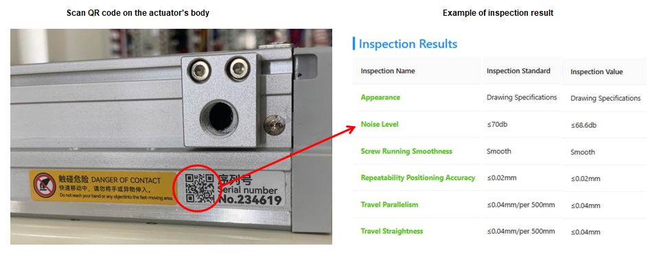
The actual test results are accessible by scanning the QR code on the actuator body.
The aluminum alloy base is directly embedded in the steel track and then ground, the walking height and straightness accuracy are improved, up to ±0.02 or less.
Small size, easy to assemble
■ Low runing noise guaranteed
Every actuator's noise level is tested before shipment to ensure runing noise level below 70 dB
Test conditions:
- Noise level is measured in an inspection room without external environmental noise and includes motor noise.
- The noise meter is placed at a distance of 300 mm.

The actual test results are accessible by scanning the QR code on the actuator body.

Dimensional Drawing
■Material / Surface Treatment| Components | Body | Embedded Guide | Ball Screw | Ball Screw Nut | Slide Block | Steel Strip |
 Material Material | Aluminum Alloy | Bearing Steel | Carbon Steel | Alloy Steel | Aluminum Alloy | Stainless Steel |
 Surface Treatment Surface Treatment | Clear Anodized | - | - | - | Clear Anodized | - |

■BC Motor (Motor Direct)

Unit (mm)

Unit (mm)
| Effective Stroke | 50 | 100 | 150 | 200 | 250 | 300 | 350 | 400 | 450 | 500 | 550 | 600 | 650 | 700 | 750 | 800 | 850 | 900 | 950 | 1000 | 1050 | 1100 |
| L | 328 | 378 | 428 | 478 | 528 | 578 | 628 | 678 | 728 | 778 | 828 | 878 | 928 | 978 | 1028 | 1078 | 1128 | 1178 | 1228 | 1278 | 1328 | 1378 |
| A | 50 | 100 | 50 | 100 | 50 | 100 | 50 | 100 | 50 | 100 | 50 | 100 | 50 | 100 | 50 | 100 | 50 | 100 | 50 | 100 | 50 | 100 |
| M | 1 | 1 | 2 | 2 | 3 | 3 | 4 | 4 | 5 | 5 | 6 | 6 | 7 | 7 | 8 | 8 | 9 | 9 | 10 | 10 | 11 | 11 |
| N | 6 | 6 | 8 | 8 | 10 | 10 | 12 | 12 | 14 | 14 | 16 | 16 | 18 | 18 | 20 | 20 | 22 | 22 | 24 | 24 | 26 | 26 |
| P | 50 | 100 | 150 | 200 | 250 | 300 | 350 | 400 | 450 | 500 | 550 | 600 | 650 | 700 | 750 | 800 | 850 | 900 | 950 | 1000 | 1050 | 1100 |
| Mass (kg) | 3.91 | 4.29 | 4.70 | 5.00 | 5.35 | 5.68 | 6.00 | 6.35 | 6.64 | 6.97 | 7.41 | 7.71 | 8.12 | 8.41 | 8.65 | 8.96 | 9.37 | 9.62 | 10.01 | 10.28 | 10.70 | 11.12 |
■BM Motor (Down Folded)

Unit (mm)
| Effective Stroke | 50 | 100 | 150 | 200 | 250 | 300 | 350 | 400 | 450 | 500 | 550 | 600 | 650 | 700 | 750 | 800 | 850 | 900 | 950 | 1000 | 1050 | 1100 |
| L | 314.5 | 364.5 | 414.5 | 464.5 | 514.5 | 564.5 | 614.5 | 664.5 | 714.5 | 764.5 | 814.5 | 864.5 | 914.5 | 964.5 | 1014.5 | 1064.5 | 1114.5 | 1164.5 | 1214.5 | 1264.5 | 1314.5 | 1364.5 |
| A | 50 | 100 | 50 | 100 | 50 | 100 | 50 | 100 | 50 | 100 | 50 | 100 | 50 | 100 | 50 | 100 | 50 | 100 | 50 | 100 | 50 | 100 |
| M | 0 | 0 | 1 | 1 | 2 | 2 | 3 | 3 | 4 | 4 | 5 | 5 | 6 | 6 | 7 | 7 | 8 | 8 | 9 | 9 | 10 | 10 |
| N | 4 | 4 | 6 | 6 | 8 | 8 | 10 | 10 | 12 | 12 | 14 | 14 | 16 | 16 | 18 | 18 | 20 | 20 | 22 | 22 | 24 | 24 |
| P | 50 | 100 | 150 | 200 | 250 | 300 | 350 | 400 | 450 | 500 | 550 | 600 | 650 | 700 | 750 | 800 | 850 | 900 | 950 | 1000 | 1050 | 1100 |
| Mass (kg) | 3.95 | 4.33 | 4.74 | 5.09 | 5.39 | 5.72 | 6.04 | 6.39 | 6.68 | 7.01 | 7.45 | 7.75 | 8.16 | 8.45 | 8.69 | 9.00 | 9.41 | 9.66 | 10.08 | 10.32 | 10.74 | 11.16 |
■BR Motor (Right Folded)
 Unit (mm)
| Effective Stroke | 50 | 100 | 150 | 200 | 250 | 300 | 350 | 400 | 450 | 500 | 550 | 600 | 650 | 700 | 750 | 800 | 850 | 900 | 950 | 1000 | 1050 | 1100 |
| L | 314.5 | 364.5 | 414.5 | 464.5 | 514.5 | 564.5 | 614.5 | 664.5 | 714.5 | 764.5 | 814.5 | 864.5 | 914.5 | 964.5 | 1014.5 | 1064.5 | 1114.5 | 1164.5 | 1214.5 | 1264.5 | 1314.5 | 1364.5 |
| A | 50 | 100 | 50 | 100 | 50 | 100 | 50 | 100 | 50 | 100 | 50 | 100 | 50 | 100 | 50 | 100 | 50 | 100 | 50 | 100 | 50 | 100 |
| M | 1 | 1 | 2 | 2 | 3 | 3 | 4 | 4 | 5 | 5 | 6 | 6 | 7 | 7 | 8 | 8 | 9 | 9 | 10 | 10 | 11 | 11 |
| N | 6 | 6 | 8 | 8 | 10 | 10 | 12 | 12 | 14 | 14 | 16 | 16 | 18 | 18 | 20 | 20 | 22 | 22 | 24 | 24 | 26 | 26 |
| P | 50 | 100 | 150 | 200 | 250 | 300 | 350 | 400 | 450 | 500 | 550 | 600 | 650 | 700 | 750 | 800 | 850 | 900 | 950 | 1000 | 1050 | 1100 |
| Mass (kg) | 3.95 | 4.33 | 4.74 | 5.09 | 5.39 | 5.72 | 6.04 | 6.39 | 6.68 | 7.01 | 7.45 | 7.75 | 8.16 | 8.45 | 8.69 | 9.00 | 9.41 | 9.66 | 10.08 | 10.32 | 10.74 | 11.16 |
■BL Motor (Left Folded)

Unit (mm)
| Effective Stroke | 50 | 100 | 150 | 200 | 250 | 300 | 350 | 400 | 450 | 500 | 550 | 600 | 650 | 700 | 750 | 800 | 850 | 900 | 950 | 1000 | 1050 | 1100 |
| L | 314.5 | 364.5 | 414.5 | 464.5 | 514.5 | 564.5 | 614.5 | 664.5 | 714.5 | 764.5 | 814.5 | 864.5 | 914.5 | 964.5 | 1014.5 | 1064.5 | 1114.5 | 1164.5 | 1214.5 | 1264.5 | 1314.5 | 1364.5 |
| A | 50 | 100 | 50 | 100 | 50 | 100 | 50 | 100 | 50 | 100 | 50 | 100 | 50 | 100 | 50 | 100 | 50 | 100 | 50 | 100 | 50 | 100 |
| M | 1 | 1 | 2 | 2 | 3 | 3 | 4 | 4 | 5 | 5 | 6 | 6 | 7 | 7 | 8 | 8 | 9 | 9 | 10 | 10 | 11 | 11 |
| N | 6 | 6 | 8 | 8 | 10 | 10 | 12 | 12 | 14 | 14 | 16 | 16 | 18 | 18 | 20 | 20 | 22 | 22 | 24 | 24 | 26 | 26 |
| P | 50 | 100 | 150 | 200 | 250 | 300 | 350 | 400 | 450 | 500 | 550 | 600 | 650 | 700 | 750 | 800 | 850 | 900 | 950 | 1000 | 1050 | 1100 |
| Mass (kg) | 3.95 | 4.33 | 4.74 | 5.09 | 5.39 | 5.72 | 6.04 | 6.39 | 6.68 | 7.01 | 7.45 | 7.75 | 8.16 | 8.45 | 8.69 | 9.00 | 9.41 | 9.66 | 10.08 | 10.32 | 10.74 | 11.16 |
Specification Table

■Basic specifications
| Drive Method | Ball Screw | |
| Ball Screw | Precision | C7 |
| O.D. (mm) | Φ16 | |
| Body width (mm) | 82 | |
| Drive power (W) | 200/400 | |
| Operating Environment | General | |
| Part Number |  Lead(mm) Lead(mm) |  Stroke Stroke(50mm increments) |  Motor Position |  Motor Brand |  Motor Outpout |  Sensor position | Positioning Repeatability (mm) | Max. Payload (kg) | Max.Speed (mm/sec) | Rated Thrust (N) | ||
 Type Type | Horizontal Use | Vertical Use | 200W | 400W | ||||||||
| E-MGT8 | 5 | 50~1100 | BC (Motor Direct) BM (Down Folded) BL (Left Folded) BR (Right Folded) | M (Misumi / Mitsubishi) P (Panasonic) Y (Yaskawa) T (Delta Electronics) Z (Customized by Customer) H (Inovance) | 20 (200W) 40 (400W) | C (Motor Side) *Left Side D (Motor Opposite Side) *Right Side * For Motor Position BC and BM | ±0.01 | 50 | 15 | 250 | 683 | 1388 |
| 10 | 30 | 8 | 500 | 341 | 694 | |||||||
| 20 | 18 | 3 | 1000 | 174 | 347 | |||||||
 A motor is not included to this product and it must be purchased separately.When the stroke exceeds 600mm, ball screw resonance will occur. In this case, reduce the movement speed.Select a motor with brake for vertical use.When Z is selected as the motor brand (prepared by customer), please provide the motor model and output when placing an order. (If necessary, provide the motor mounting dimensions)As the drawings are schematic diagrams, please confirm the detailed dimensions according to CAD data.
| Part Number | Lead (mm) | Motor Output (W) | Max. Movement Speed (mm/sec) | |||||||||||||||||||||
| 50 | 100 | 150 | 200 | 250 | 300 | 350 | 400 | 450 | 500 | 550 | 600 | 650 | 700 | 750 | 800 | 850 | 900 | 950 | 1000 | 1050 | 1100 | |||
| E-MGT8 | 5 | 200 | 250 | 225 | 200 | 175 | 150 | 125 | 100 | 75 | ||||||||||||||
| 10 | 500 | 450 | 400 | 350 | 300 | 250 | 200 | 150 | ||||||||||||||||
| 20 | 1000 | 900 | 800 | 700 | 600 | 500 | 400 | 300 | ||||||||||||||||
| 5 | 400 | 250 | 225 | 200 | 175 | 150 | 125 | 100 | 75 | |||||||||||||||
| 10 | 500 | 450 | 400 | 350 | 300 | 250 | 200 | 150 | ||||||||||||||||
| 20 | 1000 | 900 | 800 | 700 | 600 | 500 | 400 | 300 | ||||||||||||||||
Values in the table are reference values calculated according to the critical speed and DN value of the ball screw.Values in the table are maximum safety speeds available for each stroke. As ball screws may resonate at longer strokes, such conditions as abnormal sound and vibration may occur when operating at the maximum speed. Therefore, the moving speed should be reduced appropriately.■Accessories
 Accessories Accessories | Accessory Name | Part Name | Quantity | |||
| Sensor | C-MSX674N-2M | 3 | ||||
| Motor connection method | BC | Coupling (mm) | 10×11(×14) Motor Side(200W) | 10×14 Motor Side (400W) | 1 | |
| BL/BR/BM | Motor End Timing Pulley | S3M-36 Teeth-14 (Combination) | 1 | |||
| Screw End Timing Pulley | S3M-36 Teeth-10 (Combination) | 1 | ||||
| Timing Belt | S3M-258-15 | 1 | ||||
Parameter of use
■Wiring Diagram

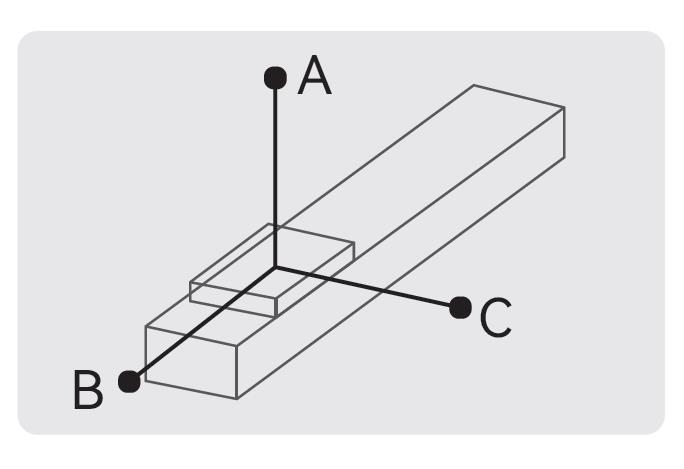
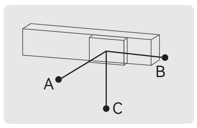
■Allowable table
Unit (mm)

Unit (mm)
| Horizontal Mount | A | B | C | |
| Lead 5 | 20kg | 1560 | 153 | 237 |
| 35kg | 890 | 81 | 126 | |
| 50kg | 550 | 53 | 82 | |
| Lead 10 | 10kg | 1730 | 286 | 412 |
| 20kg | 839 | 136 | 196 | |
| 30kg | 541 | 86 | 124 | |
| Lead 20 | 6kg | 1213 | 403 | 493 |
| 9kg | 800 | 264 | 323 | |
| 18kg | 592 | 194 | 238 | |
Unit (mm)
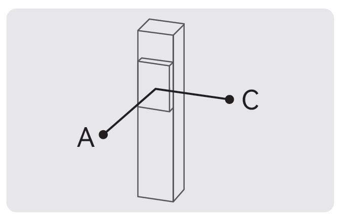
| Wall Mount | A | B | C | |
| Lead 5 | 20kg | 214 | 153 | 1435 |
| 35kg | 113 | 81 | 845 | |
| 50kg | 74 | 53 | 506 | |
| Lead 10 | 10kg | 370 | 286 | 1400 |
| 20kg | 176 | 136 | 800 | |
| 30kg | 112 | 86 | 495 | |
| Lead 20 | 6kg | 444 | 403 | 760 |
| 9kg | 292 | 264 | 277 | |
| 18kg | 214 | 194 | 544 | |
Unit (mm)
| Vertical Mount | A | C | |
| Lead 5 | 10kg | 331 | 331 |
| 15kg | 220 | 220 | |
| Lead 10 | 5kg | 589 | 589 |
| 8kg | 368 | 368 | |
| Lead 20 | 3kg | 935 | 935 |
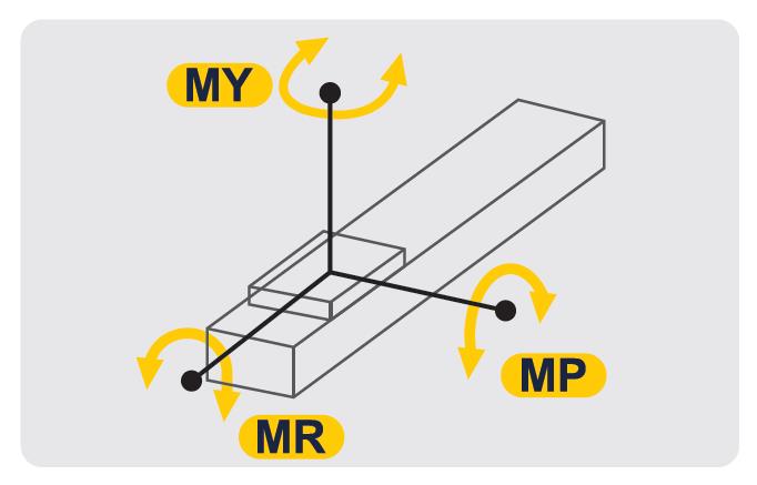
■Static allowable load inertia
Static allowable load inertia
Unit (mm)

Static allowable load inertia
Unit (mm)
| Horizontal Mount | |
| MY | 318 |
| MP | 318 |
| MR | 626 |
■List of recommendable servo motor and driver
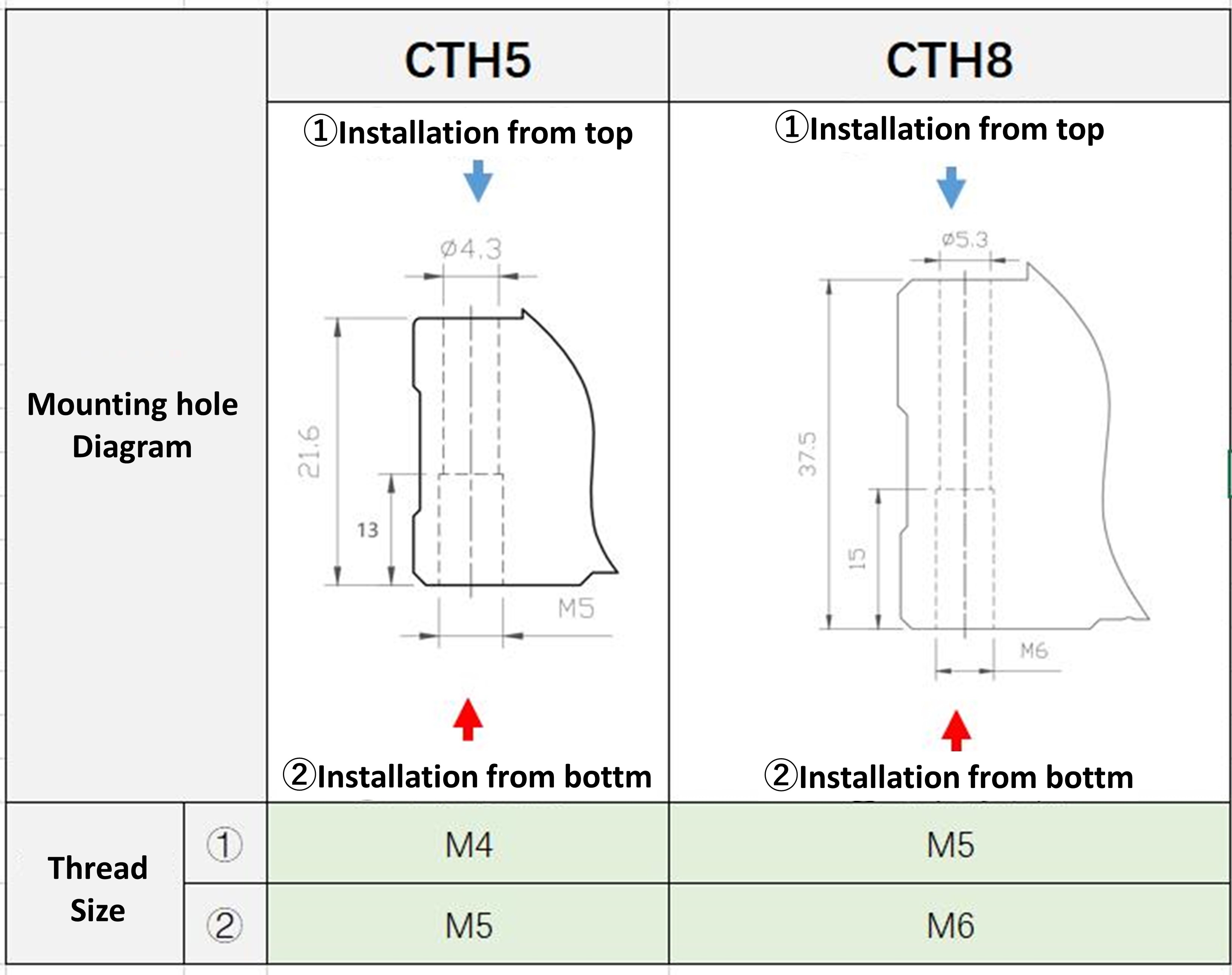
■Motor mounting hole diagram

| Brand | Motor Code | With/Without Brake | Motor Output | Voltage | Servo Motor Model | Servo Amplifier Model |
| Misumi | M | Without brake (Horizontal use) | 200W | 220V | E-MASH1-0602 | E-DFAS04P / E-DFAS04E |
| With brake (Vertical use) | E-MASH1-0602B | |||||
| Without brake (Horizontal use) | 400W | 220V | E-MASH1-0604 | |||
| With brake (Vertical use) | E-MASH1-0604B | |||||
| Mitsubishi | M | Without brake (Horizontal use) | 200W | 220V | HG-KR23J | MR-J4-20A |
| With brake (Vertical use) | HG-KR23BJ | |||||
| Without brake (Horizontal use) | 400W | 220V | HG-KR43J | MR-J4-40A | ||
| With brake (Vertical use) | HG-KR43BJ | |||||
| Panasonic | P | Without brake (Horizontal use) | 200W | 220V | MSMF022L1U2M | MADLN15SE |
| With brake (Vertical use) | MSMF022L1V2M | |||||
| Without brake (Horizontal use) | 400W | 220V | MSMF042L1U2M | MADLN25SE | ||
| With brake (Vertical use) | MSMF042L1V2M | |||||
| Yaskawa | Y | Without brake (Horizontal use) | 200W | 220V | SGM7J02AFC6S | SGD7S-1R6A00A002 |
| With brake (Vertical use) | SGM7J02AFC6E | |||||
| Without brake (Horizontal use) | 400W | 220V | SGM7J04AFC6S | SGD7S-2R8A00A002 | ||
| With brake (Vertical use) | SGM7J04AFC6E | |||||
| Delta | T | Without brake (Horizontal use) | 200W | 220V | ECMA-C20602RS | ASD-B2-0221-B |
| With brake (Vertical use) | ECMA-C20602SS | |||||
| Without brake (Horizontal use) | 400W | 220V | ECMA-C20604RS | ASD-B2-0421-B | ||
| With brake (Vertical use) | ECMA-C20604SS |
■Motor mounting hole diagram

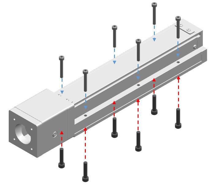
■Mounting Instruction


Product Features
1.Simple design and installation
2.Small and lightweight
3.High precision ±0.01mm
4.High rigidity
5.Low noise
6.Complete accessories
2.Small and lightweight
3.High precision ±0.01mm
4.High rigidity
5.Low noise
6.Complete accessories
Precaution
Precautions for use
■Please avoid using single-axis Actuators in the following environments
①Dust environment (especially metal powder)
②Splash water, oil environment
③Close tothe fire source
④Organic solvent, salty environment
⑤Environment with direct sunlight and heat radiation
⑥Environment with strong vibration and impact
⑦Environment with corrosive gas and flammable gas
■Single-axis Actuators operating environment
Use environment: normal temperature (no freezing, non-condensing)
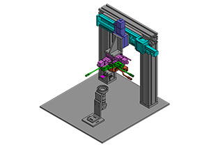
Example of Use
| Application Industry | Semiconductor |
| Purpose | Moving assembly unit using a Economy series single-axis actuator |
 | |
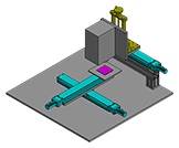
| Application | LCD detection |
| Purpose | Focus adjustment mechanism according to the size of the subject |
 | |
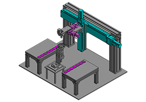
| Application | Detection |
| Purpose | Multi-axis mechanism using Economy series single-axis actuators. It supports multi-point inspection and equipment that inspects multiple workpieces at the same time. |
 | |