Round Coil Springs-Fmax. (Allowable Deflection) = Lx35%-40%/O.D. Referenced
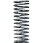
Round Coil Springs, O.D. Referenced, Piano Wire, WT / WM
Round wire compression springs standardized so that the spring constant is the same for the same outer diameter. Select WT (maximum allowable deflection 40%) or WM (28 ~ 35%) by the required stroke and load.
- Material: piano wire (SWP-A).
- Solid length is a reference value and may vary slightly by lot. Number of uses: 1,000,000 cycles.
- WT sizes marked with an asterisk in the dimension table have both end faces unground.
Part numbers and dimensions
Ordering example
| Type |
|---|
| WT13-60 |
Spring constant N/mm {kgf/mm}. WY type D12, 14 and WT type D12, 14, 20 are not available.
| D / Type | WY | WR | WF | WL | WT | WM | WH | WB | |
|---|---|---|---|---|---|---|---|---|---|
| 2 | 0.5{0.05} | ||||||||
| 3 | 0.1 {0.01} | 0.3 {0.03} | 0.5 {0.05} | 1.0 {0.1} | 1.5 {0.15} | 2.0 {0.2} | 3.9{0.4} | ||
| 4 | 2.9{0.3} | 4.9{0.5} | |||||||
| 5 | 2.0 {0.2} | 2.9 {0.3} | 5.9 {0.6} | 9.8 {1.0} | |||||
| 6 | |||||||||
| 8 | |||||||||
| 10 | 0.2 {0.02} | ||||||||
| 12 | |||||||||
| 13 | 9.8 {1.0} | 19.6{2.0} | |||||||
| 14 | |||||||||
| 16 | |||||||||
| 18 | 0.5 {0.05} | 1.0 {0.1} | 2.9 {0.3} | 3.9 {0.4} | 4.9 {0.5} | 14.7{1.5} | 29.4{3.0} | ||
| 20 | |||||||||
| 22 | 29.4{3.0} | ||||||||
| 27 | |||||||||
| Fmax. | F=L×75% | F=L×60% | F=L×45% | F=L×40% | F=L×40% | F=L×35% | F=L×30% | F=L×25% | |
WT: Fmax. (allowable deflection) = L×40% (L×35%)
| d | Solid length (reference) | F max. | Load N {kgf} max. | Type | |
|---|---|---|---|---|---|
| Type D-L | |||||
| 0.3 | 1.73 | 2 | 2.9{0.3} | WT3- | 5* |
| 0.4 | 5 | 4 | 5.9{0.6} | 10* | |
| 0.45 | 8.78 | 6 | 8.8{0.9} | 15* | |
| 0.45 | 8.78 | 8 | 11.8{1.2} | 20* | |
| 0.5 | 14.5 | 10 | 14.7{1.5} | 25* | |
| 0.4 | 2.7 | 2 | 2.9{0.3} | WT4- | 5* |
| 0.4 | 2.7 | 4 | 5.9{0.6} | 10* | |
| 0.5 | 6.5 | 6 | 8.8{0.9} | 15* | |
| 0.55 | 9.63 | 8 | 11.8{1.2} | 20 | |
| 0.55 | 9.63 | 10 | 14.7{1.5} | 25 | |
| 0.6 | 15 | 12 | 17.7{1.8} | 30 | |
| 0.6 | 15 | 14 | 20.6{2.1} | 35 | |
| 0.65 | 22.1 | 16 | 23.5{2.4} | 40 | |
| 0.45 | 2.36 | 2 | 3.9{0.4} | WT5- | 5* |
| 0.5 | 3.25 | 4 | 7.8{0.8} | 10* | |
| 0.6 | 6.3 | 6 | 11.8{1.2} | 15 | |
| 0.6 | 6.3 | 8 | 15.7{1.6} | 20 | |
| 0.7 | 12.6 | 10 | 19.6{2.0} | 25 | |
| 0.7 | 12.6 | 12 | 23.5{2.4} | 30 | |
| 0.75 | 17.3 | 14 | 27.5{2.8} | 35 | |
| 0.75 | 17.3 | 14 | 27.5{2.8} | (40) | |
| 0.8 | 24 | 15.8 | 30.9{3.2} | (45) | |
| 0.8 | 24 | 17.5 | 34.3{3.5} | (50) | |
| 0.85 | 32.3 | 19.3 | 37.8{3.9} | (55) | |
| 0.85 | 32.3 | 21 | 41.2{4.2} | (60) | |
| 0.85 | 34 | 22.7 | 44.5{4.5} | (65) | |
| 0.9 | 44.6 | 24.5 | 48.1{4.9} | (70) | |
| 0.5 | 2.38 | 2 | 3.9{0.4} | WT6- | 5* |
| 0.6 | 4.35 | 4 | 7.8{0.8} | 10 | |
| 0.6 | 4.35 | 6 | 11.8{1.2} | 15 | |
| 0.7 | 7.7 | 8 | 15.7{1.6} | 20 | |
| 0.7 | 7.7 | 10 | 19.6{2.0} | 25 | |
| 0.8 | 14 | 12 | 23.5{2.4} | 30 | |
| 0.8 | 14 | 14 | 27.5{2.8} | 35 | |
| 0.85 | 18.7 | 16 | 31.4{3.2} | 40 | |
| 0.85 | 18.7 | 18 | 35.3{3.6} | 45 | |
| 0.9 | 24.8 | 20 | 39.2{4.0} | 50 | |
| 0.9 | 24.8 | 19 | 37.8{3.9} | (55) | |
| 0.9 | 24.8 | 21 | 41.2{4.2} | (60) | |
| 0.9 | 26.1 | 22.7 | 44.5{4.5} | (65) | |
| 1 | 43 | 24.5 | 48.1{4.9} | (70) | |
| 1 | 43 | 28 | 54.9{5.6} | (80) | |
| d | Solid length (reference) | F max. | Load N {kgf} max. | Type | |
|---|---|---|---|---|---|
| Type D-L | |||||
| 0.7 | 4.38 | 4 | 7.8{0.8} | WT8- | 10 |
| 0.8 | 6.8 | 6 | 11.8{1.2} | 15 | |
| 0.8 | 6.8 | 8 | 15.7{1.6} | 20 | |
| 0.8 | 6.8 | 10 | 19.6{2.0} | 25 | |
| 0.9 | 10.8 | 12 | 23.5{2.4} | 30 | |
| 0.9 | 10.8 | 14 | 27.5{2.8} | 35 | |
| 1 | 17.5 | 16 | 31.4{3.2} | 40 | |
| 1 | 17.5 | 18 | 35.3{3.6} | 45 | |
| 1 | 17.5 | 20 | 39.2{4.0} | 50 | |
| 1.1 | 27.5 | 22 | 43.1{4.4} | 55 | |
| 1.1 | 27.5 | 24 | 47.1{4.8} | 60 | |
| 1.1 | 27.5 | 26 | 51.0{5.2} | 65 | |
| 1.1 | 27.5 | 28 | 54.9{5.6} | 70 | |
| 1.2 | 42 | 32 | 62.8{6.4} | 80 | |
| 0.85 | 5.53 | 4 | 7.8{0.8} | WT10- | 10 |
| 0.9 | 6.75 | 6 | 11.8{1.2} | 15 | |
| 0.9 | 6.75 | 8 | 15.7{1.6} | 20 | |
| 1 | 10 | 10 | 19.6{2.0} | 25 | |
| 1 | 10 | 12 | 23.5{2.4} | 30 | |
| 1 | 10 | 14 | 27.5{2.8} | 35 | |
| 1 | 10 | 16 | 31.4{3.2} | 40 | |
| 1.1 | 14.3 | 18 | 35.3{3.6} | 45 | |
| 1.1 | 14.3 | 20 | 39.2{4.0} | 50 | |
| 1.2 | 21.6 | 22 | 43.1{4.4} | 55 | |
| 1.2 | 21.6 | 24 | 47.1{4.8} | 60 | |
| 1.2 | 21.6 | 26 | 51.0{5.2} | 65 | |
| 1.3 | 32.5 | 28 | 54.9{5.6} | 70 | |
| 1.3 | 32.5 | 32 | 62.8{6.4} | 80 | |
| 1 | 6 | 6 | 11.8{1.2} | WT13- | 15 |
| 1.1 | 8.25 | 8 | 15.7{1.6} | 20 | |
| 1.1 | 8.25 | 10 | 19.6{2.0} | 25 | |
| 1.2 | 11.1 | 12 | 23.5{2.4} | 30 | |
| 1.2 | 11.1 | 14 | 27.5{2.8} | 35 | |
| 1.2 | 11.1 | 16 | 31.4{3.2} | 40 | |
| 1.2 | 11.1 | 18 | 35.3{3.6} | 45 | |
| 1.3 | 15.6 | 20 | 39.2{4.0} | 50 | |
| 1.3 | 15.6 | 22 | 43.1{4.4} | 55 | |
| 1.3 | 15.6 | 24 | 47.1{4.8} | 60 | |
| 1.4 | 21 | 26 | 51.0{5.2} | 65 | |
| 1.4 | 21 | 28 | 54.9{5.6} | 70 | |
| 1.4 | 21 | 32 | 62.8{6.4} | 80 | |
| 1.2 | 7.5 | 6 | 11.8{1.2} | WT16- | 15 |
| 1.3 | 9.43 | 8 | 15.7{1.6} | 20 | |
| 1.4 | 12.6 | 10 | 19.6{2.0} | 25 | |
| 1.4 | 12.6 | 12 | 23.5{2.4} | 30 | |
| 1.4 | 12.6 | 14 | 27.5{2.8} | 35 | |
| 1.4 | 12.6 | 16 | 31.4{3.2} | 40 | |
| 1.6 | 22.4 | 18 | 35.3{3.6} | 45 | |
| 1.6 | 22.4 | 20 | 39.2{4.0} | 50 | |
| 1.6 | 22.4 | 22 | 43.1{4.4} | 55 | |
| 1.7 | 28.9 | 24 | 47.1{4.8} | 60 | |
| 1.7 | 28.9 | 26 | 51.0{5.2} | 65 | |
| 1.7 | 28.9 | 28 | 54.9{5.6} | 70 | |
| 1.7 | 28.9 | 32 | 62.8{6.4} | 80 | |
| d | Solid length (reference) | F max. | Load N {kgf} max. | Type | |
|---|---|---|---|---|---|
| Type D-L | |||||
| 1.6 | 10.8 | 8 | 31.4{3.2} | WT18- | 20 |
| 1.7 | 13.6 | 10 | 39.2{4.0} | 25 | |
| 1.7 | 13.6 | 12 | 47.1{4.8} | 30 | |
| 1.7 | 13.6 | 14 | 54.9{5.6} | 35 | |
| 1.8 | 16.7 | 16 | 62.8{6.4} | 40 | |
| 1.9 | 20.5 | 18 | 70.6{7.2} | 45 | |
| 1.9 | 20.5 | 20 | 78.5{8.0} | 50 | |
| 2 | 26 | 22 | 86.3{8.8} | 55 | |
| 2 | 26 | 24 | 94.1{9.6} | 60 | |
| 2 | 26 | 26 | 102.0{10.4} | 65 | |
| 2 | 26 | 28 | 109.8{11.2} | 70 | |
| 2.1 | 31.5 | 32 | 125.5{12.8} | 80 | |
| 1.8 | 11.3 | 8 | 31.4{3.2} | WT22- | 20 |
| 1.8 | 11.3 | 10 | 39.2{4.0} | 25 | |
| 1.9 | 13.3 | 12 | 47.1{4.8} | 30 | |
| 1.9 | 13.3 | 14 | 54.9{5.6} | 35 | |
| 2 | 16 | 16 | 62.8{6.4} | 40 | |
| 2.1 | 19.5 | 18 | 70.6{7.2} | 45 | |
| 2.1 | 19.5 | 20 | 78.5{8.0} | 50 | |
| 2.3 | 28.2 | 22 | 86.3{8.8} | 55 | |
| 2.3 | 28.2 | 24 | 94.1{9.6} | 60 | |
| 2.3 | 28.2 | 26 | 102.0{10.4} | 65 | |
| 2.3 | 28.2 | 28 | 109.8{11.2} | 70 | |
| 2.4 | 33.6 | 32 | 125.5{12.8} | 80 | |
| 2.1 | 13.2 | 12 | 47.1{4.8} | WT27- | 30 |
| 2.3 | 17.9 | 14 | 54.9{5.6} | 35 | |
| 2.3 | 17.9 | 16 | 62.8{6.4} | 40 | |
| 2.4 | 20.4 | 18 | 70.6{7.2} | 45 | |
| 2.6 | 28.6 | 20 | 78.5{8.0} | 50 | |
| 2.6 | 28.6 | 22 | 86.3{8.8} | 55 | |
| 2.6 | 28.6 | 24 | 94.1{9.6} | 60 | |
| 2.6 | 28.6 | 26 | 102.0{10.4} | 65 | |
| 2.8 | 39.2 | 28 | 109.8{11.2} | 70 | |
| 2.8 | 39.2 | 32 | 125.5{12.8} | 80 | |
- Load calculation: load = spring constant × deflection
(SI units) N = N/mm × F mm; kgf = kgf/mm × F mm
(kgf=N×0.101972)
Allowable deflection by size (L): WT5-40 Fmax. = L×35%, WT5-45 Fmax. = L×35%, WT5-50 Fmax. = L×35%, WT5-55 Fmax. = L×35%, WT5-60 Fmax. = L×35%, WT5-65 Fmax. = L×35%, WT5-70 Fmax. = L×35%, WT6-55 Fmax. = L×35%, WT6-60 Fmax. = L×35%, WT6-65 Fmax. = L×35%, WT6-70 Fmax. = L×35%, WT6-80 Fmax. = L×35%. WT types marked * have unground end faces.
Solid length is a reference value.
Values vary slightly between lots.
Service life: 1 million cycles
WM: Fmax. (allowable deflection) = L×35%
| d | Solid length (reference) | F max. | Load N {kgf} max. | Type | ||
|---|---|---|---|---|---|---|
| Type D-L | ||||||
| 0.35 | 2.5 | 1.8 | 3.4{0.4} | WM | 3- | 5* |
| 0.38 | 3.3 | 3.5 | 6.9{0.7} | 10* | ||
| 0.45 | 7 | 5.3 | 10.3{1.1} | 15* | ||
| 0.5 | 11.5 | 7 | 13.7{1.4} | 20* | ||
| 0.5 | 11.5 | 7.5 | 14.7{1.5} | (25) | ||
| 0.55 | 20.4 | 9 | 17.7{1.8} | (30) | ||
| 0.4 | 2.3 | 1.7 | 3.9{0.4} | WM | 4- | 5* |
| 0.45 | 3.4 | 3.5 | 6.9{0.7} | 10* | ||
| 0.5 | 5.1 | 5.2 | 10.8{1.1} | 15* | ||
| 0.55 | 7.7 | 7 | 13.7{1.4} | 20 | ||
| 0.6 | 11.7 | 8.7 | 17.7{1.8} | 25 | ||
| 0.6 | 11.7 | 10.5 | 20.6{2.1} | 30 | ||
| 0.65 | 17.6 | 12.2 | 24.0{2.5} | 35 | ||
| 0.65 | 17.6 | 12 | 23.5{2.4} | (40) | ||
| 0.5 | 2.8 | 1.7 | 4.9{0.5} | WM | 5- | 5* |
| 0.6 | 4.2 | 3.5 | 9.8{1.0} | 10 | ||
| 0.65 | 6.5 | 5.2 | 14.7{1.5} | 15 | ||
| 0.65 | 6.5 | 7 | 20.6{2.1} | 20 | ||
| 0.7 | 9.1 | 8.7 | 25.5{2.6} | 25 | ||
| 0.75 | 12.7 | 10.5 | 30.4{3.1} | 30 | ||
| 0.8 | 17.4 | 12.2 | 35.3{3.6} | 35 | ||
| 0.85 | 23.8 | 14 | 41.2{4.2} | 40 | ||
| 0.85 | 23.8 | 15.8 | 46.1{4.7} | 45 | ||
| 0.9 | 23.8 | 15 | 43.5{4.5} | (50) | ||
| 0.9 | 30 | 16.5 | 49.0{5.0} | (55) | ||
| 0.9 | 30 | 18 | 53.0{5.4} | (60) | ||
| 0.9 | 30 | 17.6 | 52.0{5.3} | (65) | ||
| 0.9 | 30 | 19.6 | 58.8{6.0} | (70) | ||
| 0.55 | 2.8 | 1.7 | 4.9{0.5} | WM | 6- | 5* |
| 0.65 | 4.7 | 3.5 | 9.8{1.0} | 10 | ||
| 0.75 | 8 | 5.2 | 14.7{1.5} | 15 | ||
| 0.75 | 8 | 7 | 20.6{2.1} | 20 | ||
| 0.85 | 13.6 | 8.7 | 25.5{2.6} | 25 | ||
| 0.85 | 13.6 | 10.5 | 30.4{3.1} | 30 | ||
| 0.9 | 18 | 12.2 | 35.3{3.6} | 35 | ||
| 0.9 | 18 | 14 | 41.2{4.2} | 40 | ||
| 0.9 | 18 | 15.8 | 46.1{4.7} | 45 | ||
| 0.85 | 18 | 17.5 | 51.0{5.2} | 50 | ||
| 1.0 | 31 | 19.2 | 55.9{5.7} | 55 | ||
| 1.0 | 31 | 18 | 53.0{5.4} | (60) | ||
| 1.0 | 31 | 18.8 | 54.9{5.6} | (65) | ||
| 1.1 | 47.3 | 20 | 58.8{6.0} | (70) | ||
| 1.1 | 48.4 | 22.4 | 65.9{6.7} | (80) | ||
| 0.75 | 4.2 | 3.5 | 9.8{1.0} | WM | 8- | 10 |
| 0.9 | 8.5 | 5.2 | 14.7{1.5} | 15 | ||
| 0.9 | 8.5 | 7 | 20.6{2.1} | 20 | ||
| 0.9 | 8.5 | 8.7 | 25.5{2.6} | 25 | ||
| 0.9 | 8.5 | 10.5 | 30.4{3.1} | 30 | ||
| 1.0 | 13 | 12.2 | 35.3{3.6} | 35 | ||
| 1.0 | 13 | 14 | 41.2{4.2} | 40 | ||
| 1.1 | 19.8 | 15.8 | 46.1{4.7} | 45 | ||
| 1.1 | 19.8 | 17.5 | 51.0{5.2} | 50 | ||
| 1.2 | 31.2 | 19.2 | 55.9{5.7} | 55 | ||
| 1.2 | 31.2 | 21 | 61.8{6.3} | 60 | ||
| 1.2 | 31.2 | 22.7 | 64.7{6.6} | 65 | ||
| 1.2 | 31.2 | 24.5 | 71.6{7.3} | 70 | ||
| 1.3 | 44.2 | 28 | 82.4{8.4} | 80 | ||
| d | Solid length (reference) | F max. | Load N {kgf} max. | Type | ||
|---|---|---|---|---|---|---|
| Type D-L | ||||||
| 0.9 | 5.2 | 3.5 | 9.8{1.0} | WM | 10- | 10 |
| 1.0 | 7.7 | 5.2 | 14.7{1.5} | 15 | ||
| 1.0 | 7.7 | 7 | 20.6{2.1} | 20 | ||
| 1.1 | 11 | 8.7 | 25.5{2.6} | 25 | ||
| 1.1 | 11 | 10.5 | 30.4{3.1} | 30 | ||
| 1.2 | 16.2 | 12.2 | 35.3{3.6} | 35 | ||
| 1.2 | 16.2 | 14 | 41.2{4.2} | 40 | ||
| 1.3 | 22.1 | 15.8 | 46.1{4.7} | 45 | ||
| 1.3 | 22.1 | 17.5 | 51.0{5.2} | 50 | ||
| 1.3 | 22.1 | 19.2 | 55.9{5.7} | 55 | ||
| 1.4 | 32.1 | 21 | 61.8{6.3} | 60 | ||
| 1.4 | 32.1 | 22.7 | 64.7{6.6} | 65 | ||
| 1.4 | 32.1 | 24.5 | 71.6{7.3} | 70 | ||
| 1.4 | 32.2 | 28 | 82.4{8.4} | 80 | ||
| 1.0 | 5.5 | 3.5 | 10.3{1.1} | WM | 12- | 10 |
| 1.1 | 7.4 | 5.2 | 14.7{1.5} | 15 | ||
| 1.1 | 7.4 | 7 | 20.6{2.1} | 20 | ||
| 1.1 | 7.4 | 8.7 | 25.5{2.6} | 25 | ||
| 1.2 | 10.2 | 10.5 | 30.4{3.1} | 30 | ||
| 1.2 | 10.2 | 12.2 | 35.3{3.6} | 35 | ||
| 1.3 | 14.3 | 14 | 41.2{4.2} | 40 | ||
| 1.3 | 14.3 | 15.8 | 46.1{4.7} | 45 | ||
| 1.3 | 14.3 | 17.5 | 51.0{5.2} | 50 | ||
| 1.4 | 19.6 | 19.2 | 55.9{5.7} | 55 | ||
| 1.4 | 19.6 | 21 | 61.8{6.3} | 60 | ||
| 1.5 | 26.3 | 22.7 | 64.7{6.6} | 65 | ||
| 1.5 | 26.3 | 24.5 | 71.6{7.3} | 70 | ||
| 1.6 | 36.8 | 28 | 82.4{8.4} | 80 | ||
| 1.0 | 5 | 3.5 | 10.3{1.1} | WM | 13- | 10 |
| 1.2 | 8.4 | 5.2 | 14.7{1.5} | 15 | ||
| 1.3 | 11.7 | 7 | 20.6{2.1} | 20 | ||
| 1.3 | 11.7 | 8.7 | 25.5{2.6} | 25 | ||
| 1.4 | 14.5 | 10.5 | 30.4{3.1} | 30 | ||
| 1.4 | 14.5 | 12.2 | 35.3{3.6} | 35 | ||
| 1.4 | 14.5 | 14 | 41.2{4.2} | 40 | ||
| 1.4 | 14.5 | 15.8 | 46.1{4.7} | 45 | ||
| 1.4 | 14.5 | 17.5 | 51.0{5.2} | 50 | ||
| 1.5 | 22.5 | 19.2 | 55.9{5.7} | 55 | ||
| 1.5 | 22.5 | 21 | 61.8{6.3} | 60 | ||
| 1.6 | 28.8 | 22.7 | 64.7{6.6} | 65 | ||
| 1.6 | 28.8 | 24.5 | 71.6{7.3} | 70 | ||
| 1.7 | 37.4 | 28 | 82.4{8.4} | 80 | ||
| 1.7 | 37.4 | 31.5 | 92.9{9.5} | 90 | ||
| 1.2 | 7.5 | 5.2 | 14.7{1.5} | WM | 14- | 15 |
| 1.3 | 9.8 | 7 | 20.6{2.1} | 20 | ||
| 1.4 | 13.3 | 8.7 | 25.5{2.6} | 25 | ||
| 1.4 | 13.3 | 10.5 | 30.4{3.1} | 30 | ||
| 1.4 | 13.3 | 12.2 | 35.3{3.6} | 35 | ||
| 1.4 | 13.3 | 14 | 41.2{4.2} | 40 | ||
| 1.5 | 17.3 | 15.8 | 46.1{4.7} | 45 | ||
| 1.5 | 17.3 | 17.5 | 51.0{5.2} | 50 | ||
| 1.5 | 17.3 | 19.2 | 55.9{5.7} | 55 | ||
| 1.6 | 23.2 | 21 | 61.8{6.3} | 60 | ||
| 1.6 | 23.2 | 22.7 | 64.7{6.6} | 65 | ||
| 1.7 | 30.6 | 24.5 | 71.6{7.3} | 70 | ||
| 1.7 | 30.6 | 28 | 82.4{8.4} | 80 | ||
| 1.8 | 39.6 | 31.5 | 92.7{9.5} | 90 | ||
| d | Solid length (reference) | F max. | Load N {kgf} max. | Type | ||
|---|---|---|---|---|---|---|
| Type D-L | ||||||
| 1.3 | 7.8 | 5.2 | 14.7{1.5} | WM | 16- | 15 |
| 1.4 | 9.8 | 7 | 20.6{2.1} | 20 | ||
| 1.5 | 12.5 | 8.7 | 25.5{2.6} | 25 | ||
| 1.5 | 12.5 | 10.5 | 30.4{3.1} | 30 | ||
| 1.6 | 15 | 12.2 | 35.3{3.6} | 35 | ||
| 1.6 | 15 | 14 | 41.2{4.2} | 40 | ||
| 1.7 | 20.4 | 15.8 | 46.1{4.7} | 45 | ||
| 1.7 | 20.4 | 17.5 | 51.0{5.2} | 50 | ||
| 1.8 | 27 | 19.2 | 55.9{5.7} | 55 | ||
| 1.8 | 27 | 21 | 61.8{6.3} | 60 | ||
| 1.8 | 27 | 22.7 | 64.7{6.6} | 65 | ||
| 1.8 | 27 | 24.5 | 71.6{7.3} | 70 | ||
| 1.8 | 27 | 28 | 82.4{8.4} | 80 | ||
| 1.9 | 34.2 | 31.5 | 92.7{9.5} | 90 | ||
| 1.7 | 11.9 | 7 | 34.3{3.5} | WM | 18- | 20 |
| 1.8 | 14.4 | 8.7 | 42.2{4.3} | 25 | ||
| 1.8 | 14.4 | 10.5 | 51.0{5.2} | 30 | ||
| 1.8 | 14.4 | 12.2 | 59.8{6.1} | 35 | ||
| 1.8 | 14.4 | 14 | 68.6{7.0} | 40 | ||
| 2.0 | 22 | 15.8 | 77.5{7.9} | 45 | ||
| 2.0 | 22 | 17.5 | 85.3{8.7} | 50 | ||
| 2.0 | 22 | 19.2 | 94.1{9.6} | 55 | ||
| 2.0 | 22 | 21 | 103.0{10.5} | 60 | ||
| 2.2 | 34.1 | 22.7 | 110.8{11.3} | 65 | ||
| 2.2 | 34.1 | 24.5 | 119.6{12.2} | 70 | ||
| 2.2 | 34.1 | 28 | 137.3{14.0} | 80 | ||
| 2.3 | 41.4 | 31.5 | 154.0{15.7} | 90 | ||
| 2.3 | 41.4 | 35 | 171.6{17.5} | 100 | ||
| 1.8 | 11.7 | 7 | 34.3{3.5} | WM | 20- | 20 |
| 1.8 | 11.7 | 8.7 | 42.2{4.3} | 25 | ||
| 1.9 | 14.3 | 10.5 | 51.0{5.2} | 30 | ||
| 1.9 | 14.3 | 12.2 | 59.8{6.1} | 35 | ||
| 1.9 | 14.3 | 14 | 68.6{7.0} | 40 | ||
| 2.0 | 17 | 15.8 | 77.5{7.9} | 45 | ||
| 2.0 | 17 | 17.5 | 85.3{8.7} | 50 | ||
| 2.2 | 24.8 | 19.2 | 94.1{9.6} | 55 | ||
| 2.2 | 24.8 | 21 | 103.0{10.5} | 60 | ||
| 2.2 | 24.8 | 22.7 | 110.8{11.3} | 65 | ||
| 2.2 | 24.8 | 24.5 | 119.6{12.2} | 70 | ||
| 2.4 | 36 | 28 | 137.3{14.0} | 80 | ||
| 2.4 | 36 | 31.5 | 154.0{15.7} | 90 | ||
| 2.4 | 36 | 35 | 171.6{17.5} | 100 | ||
| 1.9 | 12 | 7 | 34.3{3.5} | WM | 22- | 20 |
| 2.0 | 14 | 8.7 | 42.2{4.3} | 25 | ||
| 2.0 | 14 | 10.5 | 51.0{5.2} | 30 | ||
| 2.0 | 14 | 12.2 | 59.8{6.1} | 35 | ||
| 2.0 | 14 | 14 | 68.6{7.0} | 40 | ||
| 2.3 | 23 | 15.8 | 77.5{7.9} | 45 | ||
| 2.3 | 23 | 17.5 | 85.3{8.7} | 50 | ||
| 2.3 | 23 | 19.2 | 94.1{9.6} | 55 | ||
| 2.3 | 23 | 21 | 103.0{10.5} | 60 | ||
| 2.4 | 30 | 22.7 | 110.8{11.3} | 65 | ||
| 2.4 | 30 | 24.5 | 119.6{12.2} | 70 | ||
| 2.4 | 30 | 28 | 137.3{14.0} | 80 | ||
| 2.6 | 40 | 31.5 | 154.0{15.7} | 90 | ||
| 2.6 | 40 | 35 | 171.6{17.5} | 100 | ||
| 2.3 | 14 | 10.5 | 51.0{5.2} | WM | 27- | 30 |
| 2.4 | 17 | 12.2 | 59.8{6.1} | 35 | ||
| 2.4 | 17 | 14 | 68.6{7.0} | 40 | ||
| 2.4 | 18 | 15.8 | 77.5{7.9} | 45 | ||
| 2.6 | 23 | 17.5 | 85.3{8.7} | 50 | ||
| 2.6 | 23 | 19.2 | 94.1{9.6} | 55 | ||
| 2.6 | 23 | 21 | 103.0{10.5} | 60 | ||
| 2.8 | 31 | 22.7 | 110.8{11.3} | 65 | ||
| 2.8 | 31 | 24.5 | 119.6{12.2} | 70 | ||
| 2.8 | 31 | 28 | 137.3{14.0} | 80 | ||
| 3.0 | 43.5 | 31.5 | 154.0{15.7} | 90 | ||
| 3.0 | 43.5 | 35 | 171.6{17.5} | 100 | ||
- Load calculation: load = spring constant × deflection
Allowable deflection by size (L): WM3-25 Fmax. = L×30%, WM3-30 Fmax. = L×30%, WM4-40 Fmax. = L×30%, WM5-50 Fmax. = L×30%, WM5-55 Fmax. = L×30%, WM5-60 Fmax. = L×30%, WM5-65 Fmax. = L×27%, WM5-70 Fmax. = L×28%, WM6-60 Fmax. = L×30%, WM6-65 Fmax. = L×29%, WM6-70 Fmax. = L×28%, WM6-80 Fmax. = L×28%. WM types marked * have unground end faces.