High Precision Linear Shafts - One End Threaded One End Tapped with Undercut / One End Threaded One End Tapped with Undercut and Wrench Flats
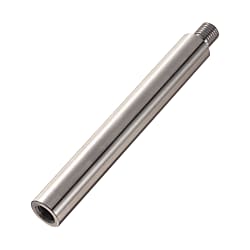
"[Features] Have a high accuracy in perpendicularity of shaft ends (0.03) and thus, are suitable for performing parts assembly that requires high accuracy."
High Precision Linear Shafts, One End Threaded, One End Tapped, with Undercut / with Wrench Flats
Linear shafts with a male-threaded end with undercut (relief groove) and a tapped end, available with or without wrench flats. Shaft-end perpendicularity of 0.03 makes them suitable for parts assembly requiring high accuracy.
- Select the type, then D, L, F, M (male thread), N (tapped thread) and, for wrench-flat types, SC.
- L, F and SC are specified in 1 mm increments. Their dimensional tolerances conform to JIS B 0405 m class, excluding the male thread chamfer tolerance.
Material, surface treatment and hardness
- Surface roughness of part D differs between plated and unplated items.
- Tolerances of dimensions L, F and SC conform to JIS B 0405 m class (male thread chamfer tolerances excluded).
| Type | D tolerance | Material | Hardness | Surface treatment | |
|---|---|---|---|---|---|
| Without wrench flats | With wrench flats | ||||
| VAFD | VAFZ | g6 | SUJ2 equivalent | Induction hardened (effective hardened depth: see table) SUJ2 equivalent 58HRC min. SUS440C or 13Cr stainless steel 56HRC min. | - |
| VSAFD | VSAFZ | SUS440C or 13Cr stainless steel | |||
| VPAFD | VPAFZ | SUJ2 equivalent | Hard chrome plating Plating hardness HV750 min. Plating thickness 5 μm min. | ||
| VPSAFD | VPSAFZ | SUS440C or 13Cr stainless steel | |||
| VRFD | VRFZ | SUJ2 equivalent | Low-temperature black chrome plating | ||
| VPSAFDG | VPSAFZG | f8 | SUS304 | - | Hard chrome plating Plating hardness HV750 min. Plating thickness 10 μm min. |
- Hard chrome plated items are machined after plating, so machined areas are not plated.
Part numbers and dimensions
Ordering example
| Type | - | L | - | F | - | M | - | N |
|---|---|---|---|---|---|---|---|---|
| VPAFD20 | - | 300 | - | F25 | - | M16 | - | N12 |
| D tolerance | ||
|---|---|---|
| D | g6 | f8 |
| 8 | -0.005 | -0.013 |
| 10 | -0.014 | -0.035 |
| 12 | -0.006 | -0.016 |
| 13 | -0.017 | -0.043 |
| 15 | ||
| 16 | ||
| 18 | ||
| 20 | -0.007 | -0.020 |
| 25 | -0.020 | -0.053 |
| 30 | ||
| Type | 1 mm increments | M (coarse) | N (coarse) | Wrench flat dimensions | (Y) | C | |||||||||||||||||||
|---|---|---|---|---|---|---|---|---|---|---|---|---|---|---|---|---|---|---|---|---|---|---|---|---|---|
| Type | D | L | F | Selection | Selection | SC | W | ℓ1 | Max. | ||||||||||||||||
| (Without wrench flats) | (With wrench flats) | 8 | 25–295 | 5≤F≤M×3 | 6 | 3 | 4 | 5 | SC: 1 mm increments | 7 | 8 | 300 | 0.5 | ||||||||||||
| D tolerance g6 | D tolerance g6 | 10 | 25–345 | 6 | 8 | 3 | 4 | 5 | 6 | 8 | 350 | Up to | |||||||||||||
| VAFD | VAFZ | 12 | 25–345 | 6 | 8 | 10 | 4 | 5 | 6 | 8 | SC+ℓ1≤L | 10 | 10 | 350 | |||||||||||
| VSAFD | VSAFZ | 13 | 25–345 | F-g≥Pitch×3 | 6 | 8 | 10 | 4 | 5 | 6 | 8 | SC≥0 | 11 | 350 | |||||||||||
| VPAFD | VPAFZ | 15 | 25–345 | 6 | 8 | 10 | 12 | 4 | 5 | 6 | 8 | 10 | 13 | 350 | |||||||||||
| VPSAFD | VPSAFZ | 16 | 25–345 | 6 | 8 | 10 | 12 | 4 | 5 | 6 | 8 | 10 | Wrench flat details | 14 | 350 | ||||||||||
| VRFD | VRFZ | 18 | 25–345 | 6 | 8 | 10 | 12 | 16 | 4 | 5 | 6 | 8 | 10 | 12 | 16 | 350 | |||||||||
| D tolerance f8 | D tolerance f8 | 20 | 25–445 | 6 | 8 | 10 | 12 | 16 | 4 | 5 | 6 | 8 | 10 | 12 | 17 | 450 | 1 | ||||||||
| VPSAFDG | VPSAFZG | 25 | 25–445 | 8 | 10 | 12 | 16 | 20 | 4 | 5 | 6 | 8 | 10 | 12 | 16 | 22 | 450 | Up to | |||||||
| 30 | 25–445 | 8 | 10 | 12 | 16 | 20 | 24 | 6 | 8 | 10 | 12 | 16 | 20 | 27 | 15 | 450 | |||||||||
| Coarse thread relief dimensions | |||
|---|---|---|---|
| M | Pitch | MC | (g) |
| 6 | 1.0 | 4.2 | 2 |
| 8 | 1.25 | 6.0 | 3 |
| 10 | 1.5 | 7.7 | |
| 12 | 1.75 | 9.4 | 4 |
| 16 | 2.0 | 13.0 | |
| 20 | 2.5 | 16.4 | 5 |
| 24 | 3.0 | 19.6 | |
| 30 | 3.5 | 25.0 | |
Male thread C chamfer details
| Nominal thread M | Pitch P | Chamfer C (reference) |
|---|---|---|
| 3 | 0.50 | 0.50 |
| 4 | 0.70 | 0.75 |
| 5 | 0.80 | 0.75 |
| 6 | 1.00 | 1.00 |
| 8 | 1.25 | 1.25 |
| 10 | 1.50 | 1.50 |
| 12 | 1.75 | 1.75 |
| 16 | 2.00 | 2.00 |
| 20 | 2.50 | 2.50 |
| 24 | 3.00 | 3.00 |
| 30 | 3.50 | 3.50 |
- Overall length L must satisfy N×3 ≤ L.
- Shaft ends may have a center hole.
Alterations
Alterations are available. Refer to the alteration table for applicable codes, dimensional limits and conditions.
For details, please see the PDF catalog.
Technical reference
Straightness measurement
Support both shaft ends on V-blocks, rotate the shaft once and measure the dial gauge amplitude at any point.
Straightness is 1/2 of the measured amplitude.
Roundness M ■Perpendicularity K ■L dimension tolerance: shafts with O.D. g6 (hardened)
| D | Roundness M | |
|---|---|---|
| Over | Up to | |
| 7 | 13 | 0.004 |
| 13 | 20 | 0.005 |
| 20 | 30 | 0.006 |
Unit: mm. Shafts with O.D. f8 (not hardened)
| D | Roundness M | |
|---|---|---|
| Over | Up to | |
| 7 | 10 | 0.011 |
| 10 | 18 | 0.014 |
| 18 | 30 | 0.017 |
Unit: mm. Shafts with O.D. g6 (hardened)
| D | L | Straightness K |
|---|---|---|
| 8–30 | L≤100 | 0.01 or less |
| L>100 | (L/100)×0.01 or less |
| L | Straightness K |
|---|---|
| L≤100 | 0.025 or less |
| L>100 | (L/100)×0.025 or less |
| L | L dimension | |
|---|---|---|
| Over | Up to | Tolerance |
| 24 | 30 | ±0.2 |
| 30 | 120 | ±0.3 |
| 120 | 400 | ±0.5 |
| 400 | 445 | ±0.8 |
Unit: mm
Hardness reduction at machined areas
- Machining is done after hardening, but annealing for machining may reduce hardness.
- *Hardness after reduction: approx. 10–40HRC
Hardness reduction range
- Approx. 10 mm from the machined area
(Example)
Areas with hardness reduced by annealing
- Male thread
• Wrench flats
• Flats
Hardness reduction at female threads: the conditions depend on material and selection.
SUS440C or 13Cr stainless steel: hardness is reduced at the female thread.
SUJ2 equivalent: under the conditions below, hardness is reduced at the female thread.
- When M ≥ D/2
• RC threads
• 2-hole female thread type
Effective hardened depth: depends on outer dimensions and material.
| O.D. D | Effective hardened depth | |
|---|---|---|
| SUJ2 equivalent | SUS440C / 13Cr stainless steel | |
| 8, 10 | 0.5 or more | 0.5 or more |
| 12, 13 | 0.7 or more | |
| 15–20 | 0.7 or more | |
| 25, 30 | 1.0 or more | |
Hard chrome plating on machined areas: hard chrome plated items are machined after plating, so machined areas are not plated.
In the example below, only the "///" area is hard chrome plated.
Example: plating remains on a stepped male-thread shaft with an added flat
Shafts vs. rotary shafts
- Specification comparison: linear shafts and rotary shafts
Basic specifications
| Specifications | Shaft | Rotary shaft | ||
|---|---|---|---|---|
| Material | SUJ2 equivalent SUS440C or 13Cr stainless steel | S45C equivalent SUS304 | S45C equivalent SUS304 | SCM435 |
| Hardening | Induction hardening | - | - | Hardness 30–35HRC |
| O.D. tolerance | g6/h5 | f8 | g6/h9/h7 | g6 |
| Surface treatment | No plating Hard chrome plating Low-temperature black chrome plating Electroless nickel plating (full-length treatment type) | Hard chrome plating | No plating Black oxide Electroless nickel plating | Black oxide Electroless nickel plating |
- *With hard chrome plating, no plating remains on machined areas.
Overview and technical notes
- Annealing for shaft end machining (effective thread length + approx. 10 mm) may reduce hardness.
Application examples
- Drilled-hole types are useful in tight spaces.